Acoustic wave filter device, radio-frequency front-end circuit, and communication apparatus

a filter device and radio frequency front-end technology, applied in the direction of transmission, electrical equipment, antenna earthing switch association, etc., can solve the problems of deteriorating the attenuation characteristic on the low-frequency side of the pass band, increasing etc., to reduce or prevent the loss within the pass band

Active Publication Date: 2019-06-20
MURATA MFG CO LTD
View PDF2 Cites 0 Cited by
  • Summary
  • Abstract
  • Description
  • Claims
  • Application Information

AI Technical Summary

Benefits of technology

[0007]Preferred embodiments of the present invention provide acoustic wave filter devices, radio-frequency front-end circuits, and communication apparatuses that are each able to reduce or prevent the loss within the pass band.

Problems solved by technology

Specifically, if the I-R pitch is excessively large, ripples at the high-frequency end of the stop band of the first parallel-arm resonator are large, resulting in an increase in loss within the pass band.
If the I-R pitch is excessively small, on the other hand, ripples in a frequency range higher than the resonant frequency (specifically, between the resonant frequency and the anti-resonant frequency) of the first parallel-arm resonator are large, resulting in an increase in loss within the pass band or deterioration of the attenuation characteristic on the low-frequency side of the pass band.

Method used


Image

  • Acoustic wave filter device, radio-frequency front-end circuit, and communication apparatus
  • Acoustic wave filter device, radio-frequency front-end circuit, and communication apparatus
  • Acoustic wave filter device, radio-frequency front-end circuit, and communication apparatus

Examples


embodiment 1

Preferred Embodiment 1

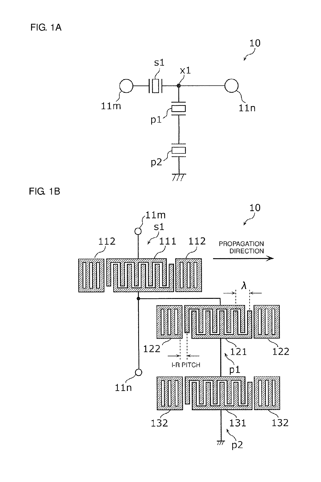
[0052]FIG. 1A is a circuit configuration diagram of a filter 10 according to a Preferred Embodiment 1 of the present invention.

[0053]The filter 10 is preferably a radio frequency filter circuit provided in a front-end portion of a multi-mode / multi-band cellular phone, for example. The filter 10 is preferably, for example, a band pass filter included in a multi-band cellular phone complying with a communication standard, such as LTE (Long Term Evolution), and configured to filter radio-frequency signals in a predetermined band. The filter 10 is preferably, for example, an acoustic wave filter device that filters radio-frequency signals using acoustic wave resonators.

[0054]As illustrated in FIG. 1A, the filter 10 includes a series-arm resonator s1 and parallel-arm resonators p1 and p2.

[0055]The series-arm resonator s1 is connected between an input / output terminal 11m (first input / output terminal) and an input / output terminal 11n (second input / output terminal). Th...

embodiment 2

Preferred Embodiment 2

[0121]The configuration of the filter 10 (acoustic wave filter device) according to the Preferred Embodiment 1 is applicable to a tunable filter having a variable pass band. Accordingly, such a tunable filter defined by a filter according to a Preferred Embodiment 2 of the present invention will be described with reference to Application Examples 1 to 6. Specifically, Application Examples 1 and 2 are application examples of the filter 10 according to the Preferred Embodiment 1 to a tunable filter. Application Examples 3 to 6 are application examples of a configuration in which the parallel-arm resonator p1 (first parallel-arm resonator) and the parallel-arm resonator p2 (second parallel-arm resonator) in the Preferred Embodiment 1 are connected in parallel to each other to a tunable filter.

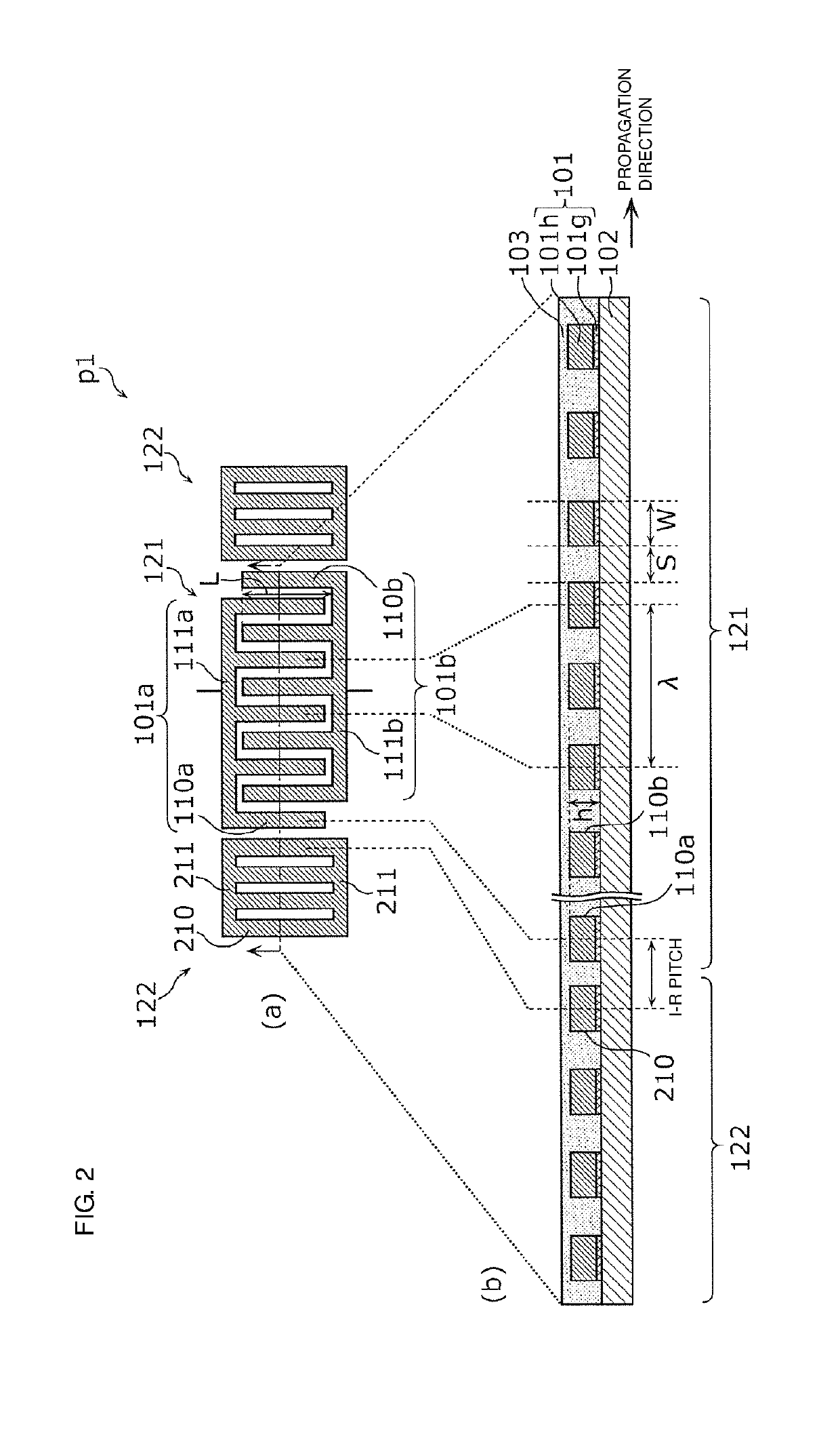
[0122]A tunable filter is also able to reduce the loss within the pass band by setting the I-R pitch (the pitch between the IDT electrode 121 and the reflectors 122) of the p...

application example 1

[0124]FIG. 7A is a circuit configuration diagram of a filter 20A in an Application Example 1 of the Preferred Embodiment 2.

[0125]Unlike the filter 10 illustrated in FIG. 1A, the filter 20A illustrated in FIG. 7A further includes a switch SW connected in parallel to one parallel-arm resonator among the parallel-arm resonators p1 and p2 (first and second parallel-arm resonators). The other parallel-arm resonator among the parallel-arm resonators p1 and p2 is connected in series with a circuit in which the one parallel-arm resonator and the switch SW are connected in parallel.

[0126]In the present application example, the switch SW is connected in parallel to the parallel-arm resonator p2. The switch SW may be connected in parallel to the parallel-arm resonator p1.

[0127]FIG. 7B is a graph depicting filter characteristics of the filter 20A in the Application Example 1 of the Preferred Embodiment 2. Specifically, FIG. 7B is a graph depicting a comparison of filter characteristics when the...


PUM


Abstract

A filter includes a series-arm resonator connected on a path connecting an input / output terminal and an input / output terminal, and first and second parallel-arm resonators connected between the same node on the path and ground. A resonant frequency of the first parallel-arm resonator is lower than a resonant frequency of the second parallel-arm resonator, and an anti-resonant frequency of the first parallel-arm resonator is lower than an anti-resonant frequency of the second parallel-arm resonator. The first parallel-arm resonator is defined by an acoustic wave resonator, and includes an IDT electrode that excites an acoustic wave, and a reflector that reflects the acoustic wave excited by the IDT electrode. A pitch between the IDT electrode and the reflector is about 0.42λ or more and less than about 0.50λ.

Description

CROSS REFERENCE TO RELATED APPLICATIONS[0001]This application claims the benefit of priority to Japanese Patent Application No. 2016-172272 filed on Sep. 2, 2016 and is a Continuation Application of PCT Application No. PCT / JP2017 / 031271 filed on Aug. 30, 2017. The entire contents of each of these applications are hereby incorporated herein by reference.BACKGROUND OF THE INVENTION1. Field of the Invention[0002]The present invention relates to an acoustic wave filter device including resonators, a radio-frequency front-end circuit, and a communication apparatus.2. Description of the Related Art[0003]An existing acoustic wave filter device, such as a ladder filter, is configured such that a single parallel arm (parallel-arm resonant circuit) connecting a series arm (series-arm resonant circuit) and ground is provided with a plurality of parallel-arm resonators (see, for example, Japanese Unexamined Patent Application Publication No. 2009-207116). In this configuration, a plurality of p...

Claims


Application Information

Patent Timeline
Patent Type & Authority Applications(United States)
IPC IPC(8): H03H9/64H03H9/145H03H9/02H01Q1/50H04B1/40
CPCH03H9/6489H03H9/6483H03H9/14544H03H9/02637H01Q1/50H04B1/40H03H9/14541H03H9/542H03H9/605H03H9/6403H04B1/0057H04B1/006H03H9/14538H03H9/6433H03H9/6496
Inventor NOSAKA, KOJI
Owner MURATA MFG CO LTD
Why Eureka
Try Eureka