
Versatile Slide Hammer Method and Apparatus

a technology of slide hammer and hammer head, which is applied in the field of slide hammer, can solve the problems of inability to easily negotiate obstacles in the path of intended impact force, increased safety of operators, and considerable set-up time, so as to increase the effectivity and safety of the repair process, and improve the control of corrective force level

Active Publication Date: 2019-06-27
CHARTIER GARY CLAUDE
View PDF0 Cites 1 Cited by
  • Summary
  • Abstract
  • Description
  • Claims
  • Application Information

AI Technical Summary

Benefits of technology

The present invention is a slide hammer apparatus that can be used to repair distorted automotive components caused by collisions or other damage. It allows for greater control and safety during the repair process by using existing equipment, such as a frame puller, and reducing static force requirements. The versatility of the slide hammer allows it to be mounted at any point along the static pull force, and it does not need to be removed between operations. This invention increases efficiency and quality of repair while improving safety for operators. It provides a better method and apparatus for repairing automotive components.

Problems solved by technology

Due to the limitations of the mounting methods, the setup time may be considerable while in some instances unsafe for the operator.
Additionally, the operator is often unable to readily negotiate obstacles in the path of the intended impact forces without reconfiguring the work environment.
The setup times combined with the lack of facility for the avoidance of obstacles reduce the overall efficiency and quality of the repair provided by prior art embodiments.
Further, the operator is often forced to neglect best practices in the pursuit of expediency during the setup phase of existing apparatus and methods and may thereby imperil their safety.

Method used


Image

  • Versatile Slide Hammer Method and Apparatus
  • Versatile Slide Hammer Method and Apparatus
  • Versatile Slide Hammer Method and Apparatus

Examples


Embodiment Construction

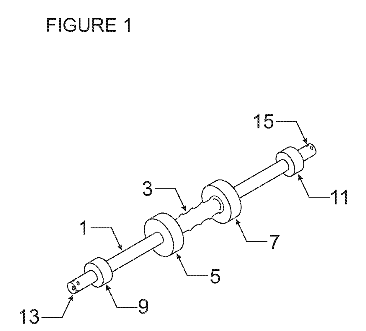
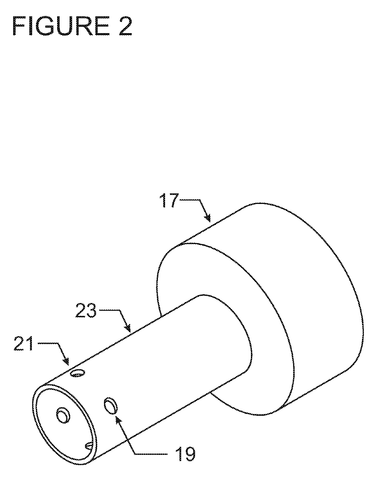
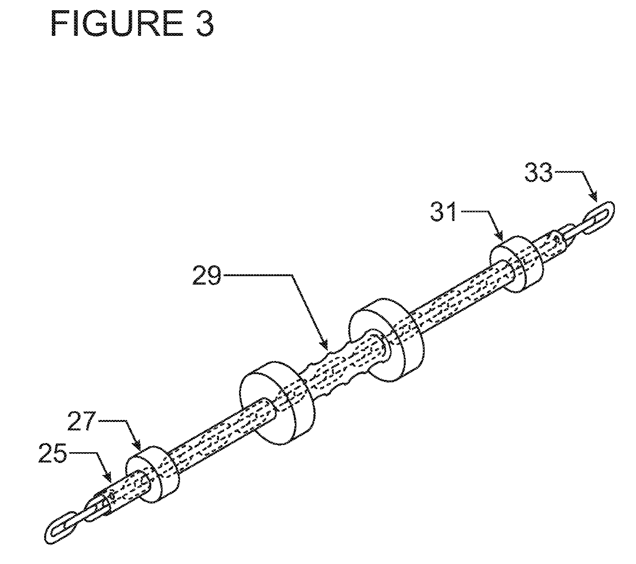
[0013]In order to better understand the embodiment of the present invention, an embodiment of the versatile slide hammer apparatus will be described with reference to FIGS. 1 through 5. An embodiment of a versatile slide hammer apparatus is provided as in FIG. 1 comprised of an hollow shaft element 1, a sliding hammer element with gripping surface 3 and first and second strike elements 5 and 7, a first stop element 9, a second stop element 11, first hollow shaft end 13, and second hollow shaft end 15. Operation of said versatile slide hammer apparatus is facilitated by the free movement of said sliding hammer element along the hollow shaft 1 between stop elements 9 and 11. Stop elements 9 and 11 are rigidly fixed to hollow shaft 1. Striking stop element 9 with strike element 5 transfers that strike force to the hollow shaft 1 along a vector passing from strike element 5 to stop element 9. Conversely, striking stop element 11 with strike element 7 transfers that strike force to the h...


PUM

PropertyMeasurementUnit
inner diameteraaaaaaaaaa
lengthaaaaaaaaaa
forcesaaaaaaaaaa

Abstract

The present invention provides a means to achieve enhanced control of repair forces in the automotive body repair industry. In particular, the present invention provides a modified slide hammer and a method to achieve repair through the controlled application of forces otherwise not attainable with existing embodiments. Additionally, the present invention provides an ease of use and versatility of application and mounting at the site of the work in conjunction with and in line with existing devices used in the repair process. The application of the present invention provides increased reliability in the delivery of intended forces at the site of the work. Further, the inherent isolation of repair forces to the intended site of the work by the use of the present invention reduces the likelihood of secondary damage, material waste, or catastrophic failure thereby also enhancing the safety of the operator and the effectivity of repair. Specifically, the present invention may be implemented in conjunction with existing frame pullers in the automotive body repair industry to affect repair while providing facility to avoid obstructions in the path of applied forces.

Description

BACKGROUND OF THE INVENTION1. Field of the Invention[0001]The present invention generally relates to slide hammers used to provide impact forces normal to the plane of the site of the work. Specifically, the present invention relates to methods and apparatus employed to deliver impact forces for the purposes of repair. The application of the present invention for the delivery of impact forces is appropriate where a static force is present and impact forces are required along the same vector. This invention finds particular application in the repair of collision related distortions of surfaces and structural elements in the automotive body repair industry wherein greater control of applied corrective forces is desirable.2. Description of the Prior Art[0002]Prior art embodiments of slide hammer apparatus are used to provide impact forces by direct connection of the ends of the hammer to the work on one side and the pulling force on the other. Such devices are generally used to provide...

Claims


Application Information

Patent Timeline
Patent Type & Authority Applications(United States)
IPC IPC(8): B25D1/16B21D1/06
CPCB25D1/16B21D1/065B25D2250/105B25D2250/171B25D2250/295
Inventor CHARTIER, GARY CLAUDE
Owner CHARTIER GARY CLAUDE
Learn More