Exhaust system for a combustion engine of a motor vehicle and motor vehicle

a technology of exhaust system and combustion engine, which is applied in the direction of engine components, mechanical equipment, transportation and packaging, etc., can solve the problems of particularly light exhaust system, and achieve the effect of reducing weight and reducing wall thickness

Active Publication Date: 2019-06-27
FAURECIA EMISSIONS CONTROL TECH GERMANY
View PDF0 Cites 3 Cited by
  • Summary
  • Abstract
  • Description
  • Claims
  • Application Information

AI Technical Summary

Benefits of technology

[0006]An exhaust system comprises a support plate on which at least one exhaust line or at least one exhaust silencer is provided. The support plate is made of a plastic material. The construction of the exhaust system according to the invention thus fundamentally differs from known exhaust systems which are formed by a self-supporting structure of exhaust lines and exhaust treatment devices, for example exhaust silencers. In the exhaust system according to the invention, the exhaust line and / or the exhaust silencer are not self-supporting. Merely the carrier plate is configured as a supporting part, and in this connection stabilises the exhaust line and / or the exhaust silencer. Thus, merely the support plate is a structural part. Therefore, materials having a comparatively lower wall thickness can be used for the exhaust line and / or the exhaust silencer. For example, metal sheets or foils having wall thickness of 0.2 mm or less may be used. This construction results in a particularly light exhaust system overall. As a result of the support plate being made of plastic material, a further weight reduction can be achieved whilst the support plate still has the necessary stability.

Problems solved by technology

This construction results in a particularly light exhaust system overall.

Method used


Image

  • Exhaust system for a combustion engine of a motor vehicle and motor vehicle
  • Exhaust system for a combustion engine of a motor vehicle and motor vehicle

Examples


Embodiment Construction

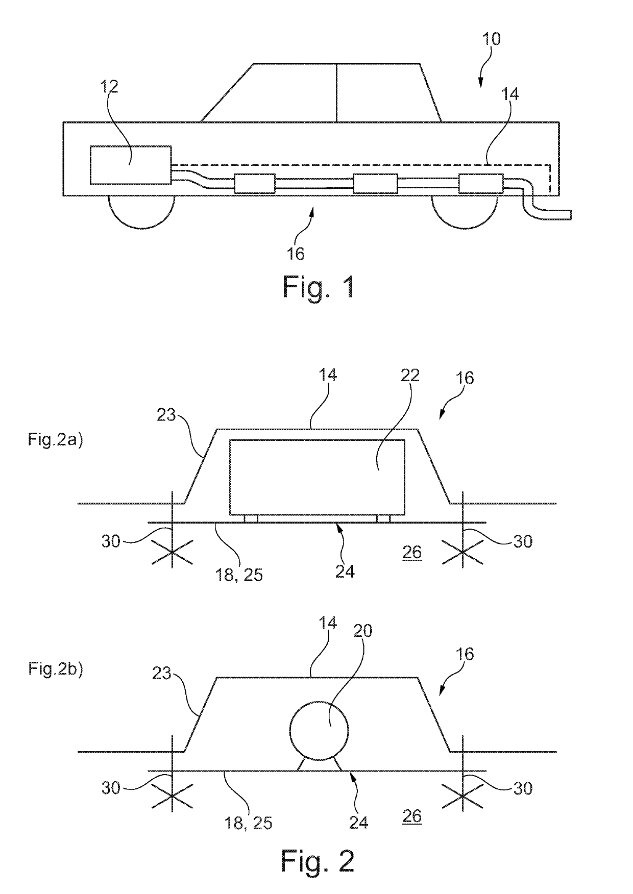
[0029]FIG. 1 shows a motor vehicle 10 comprising a combustion engine 12 and an exhaust system 16 which is arranged in an underfloor tunnel 14 of the motor vehicle 10.

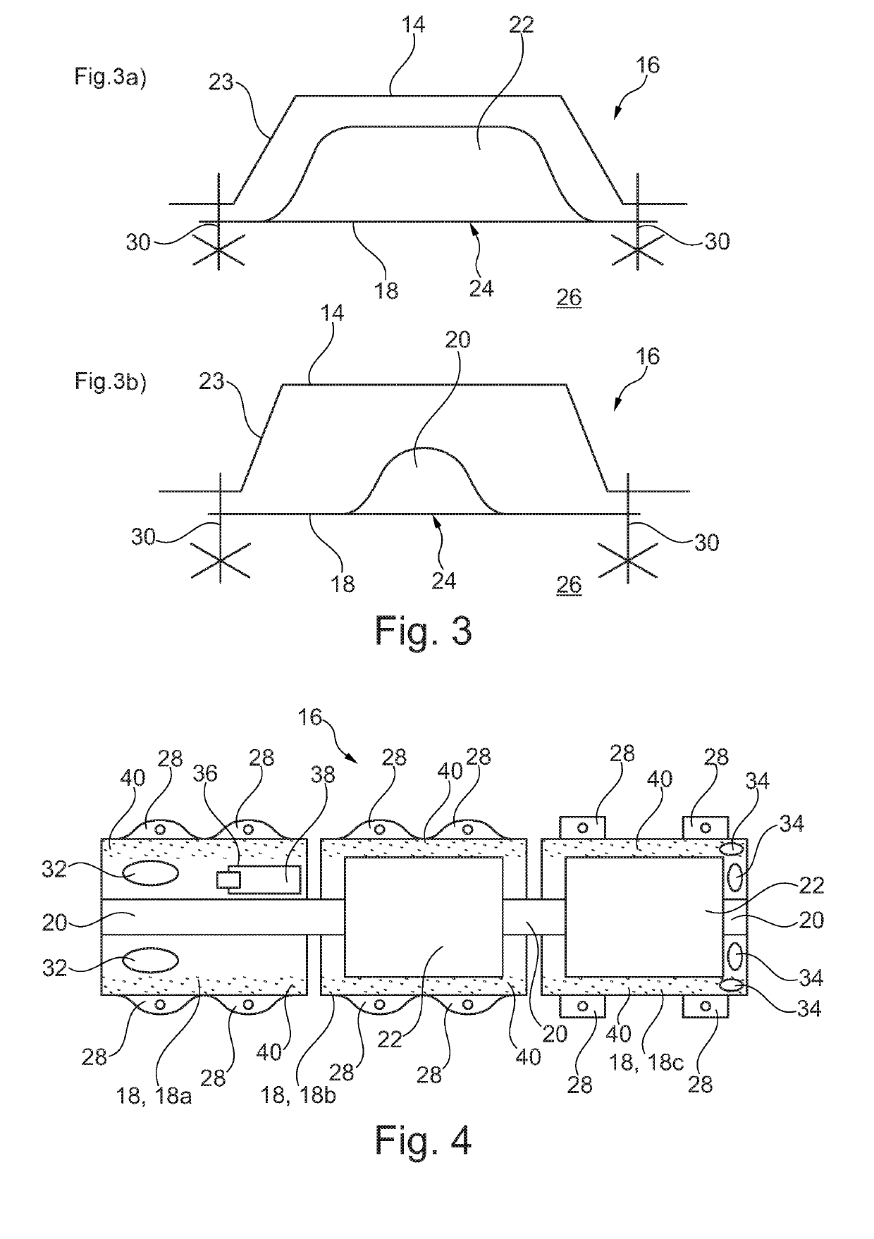
[0030]The exhaust system 16 comprises a support plate 18 on which an exhaust silencer 22 (see FIGS. 2a and 3a) or an exhaust line 20 (see FIGS. 2b and 3b) is provided.

[0031]In addition, the support plate 18 seals the underfloor tunnel 14 at least in portions on the floor side.

[0032]The underfloor tunnel 14, together with the support plate 18, thus forms an exhaust system housing 23. In this connection, the underfloor tunnel 14 forms an upper shell of the exhaust system housing 23, and the support plate 18 forms a lower shell of the exhaust system housing 23.

[0033]In the present case, the support plate 18 is made of a fibre-reinforced plastics material.

[0034]When mounted, the support plate 18 further has a drive-increasing and / or air-resistance-reducing surface 24 on the floor side. This reduces the air resistance of the...


PUM


Abstract

An exhaust system for a combustion engine of a motor vehicle comprises a support plate on which at least one exhaust line or at least one exhaust silencer is provided. The support plate is made of a plastic material. A motor vehicle comprises a combustion engine and an exhaust system which is arranged in an underfloor tunnel of the motor vehicle.

Description

CROSS-REFERENCE TO RELATED APPLICATIONS[0001]This application is a U.S. non-provisional application claiming the benefit of German Application No. 10 2017 130 866.0, filed on Dec. 21, 2017, which is incorporated herein by its entirety.FIELD OF INVENTION[0002]The invention relates to an exhaust system for a combustion engine of a motor vehicle. The invention also relates to a motor vehicle comprising a combustion engine and an exhaust system of the aforementioned type.BACKGROUND OF THE INVENTION[0003]Motor vehicles and exhaust systems are known in the art.[0004]As part of the general attempt to make motor vehicles more lightweight in such a way that, among other things, the fuel consumption and the associated CO2 emissions decrease, a general reduction in weight is likewise aimed for in the field of exhaust systems.[0005]Against this background, the object of the invention is to set out an improved exhaust system.SUMMARY OF THE INVENTION[0006]An exhaust system comprises a support pla...

Claims


Application Information

Patent Timeline
Patent Type & Authority Applications(United States)
IPC IPC(8): F01N13/18F01N13/02F01N13/08B60K13/04
CPCF01N13/1805F01N13/02F01N13/08B60K13/04
Inventor KIENLE, BORIS
Owner FAURECIA EMISSIONS CONTROL TECH GERMANY
Why Eureka
Try Eureka