System and method for enhanced treating of matter with engineered angular momentum UV photons

Active Publication Date: 2019-07-04
NUSPOT TECH LLC
View PDF0 Cites 2 Cited by
  • Summary
  • Abstract
  • Description
  • Claims
  • Application Information

AI Technical Summary

Benefits of technology

[0072]FIG. 9 is another schematic diagram illustrating the effect of the invention of using UV photons with engineered angular mo

Problems solved by technology

Warm-up times are therefore required, and during these times a given Hg vapor lamp will not provide an adequate UV irradiation level.
This implies that the single spectral emissions cannot be engineered to be enabled or disabled, red shift or blue shift; similarly, and most importantly the polarization of the emitted photons cannot be controlled either.
Similarly to other gas discharge lamps, the spectral emission of excimer lamps cannot be engineered to enable or disable desired wavelengths, red or blue shift, and control the polarization of the emitted photons.
However, similarly to other gas discharge lamps, the polarization of the emitted photons is not engineered.
Additionally, they typically require high power and high voltages; thus, they must use line voltage, and must be addressed as separate components that are not arbitrarily scalable.
This translates into a very inefficient use of photons, and a continuous need to generate and replace them.
This also creates a scenario where there the radiation field is not uniform.
In addition they are environmentally friendly because of the absence of Hg; however, differently from Hg vapor lamps, they enable zero-emission limitations because their on-off operation and their UV emission is pseudo-instantaneous and limited to only a few nanoseconds when supported by adequate electronic drivers.
With damaged nucleic acids, unicellular and multicellular organisms are unable to reproduce, and so they cannot form colonies.
Thus instead of engineering the wavelength emission of a UV source to target the exact wavelength absorbed by a given contaminant or photocatalyst,

Method used


Image

  • System and method for enhanced treating of matter with engineered angular momentum UV photons
  • System and method for enhanced treating of matter with engineered angular momentum UV photons
  • System and method for enhanced treating of matter with engineered angular momentum UV photons

Examples


Example

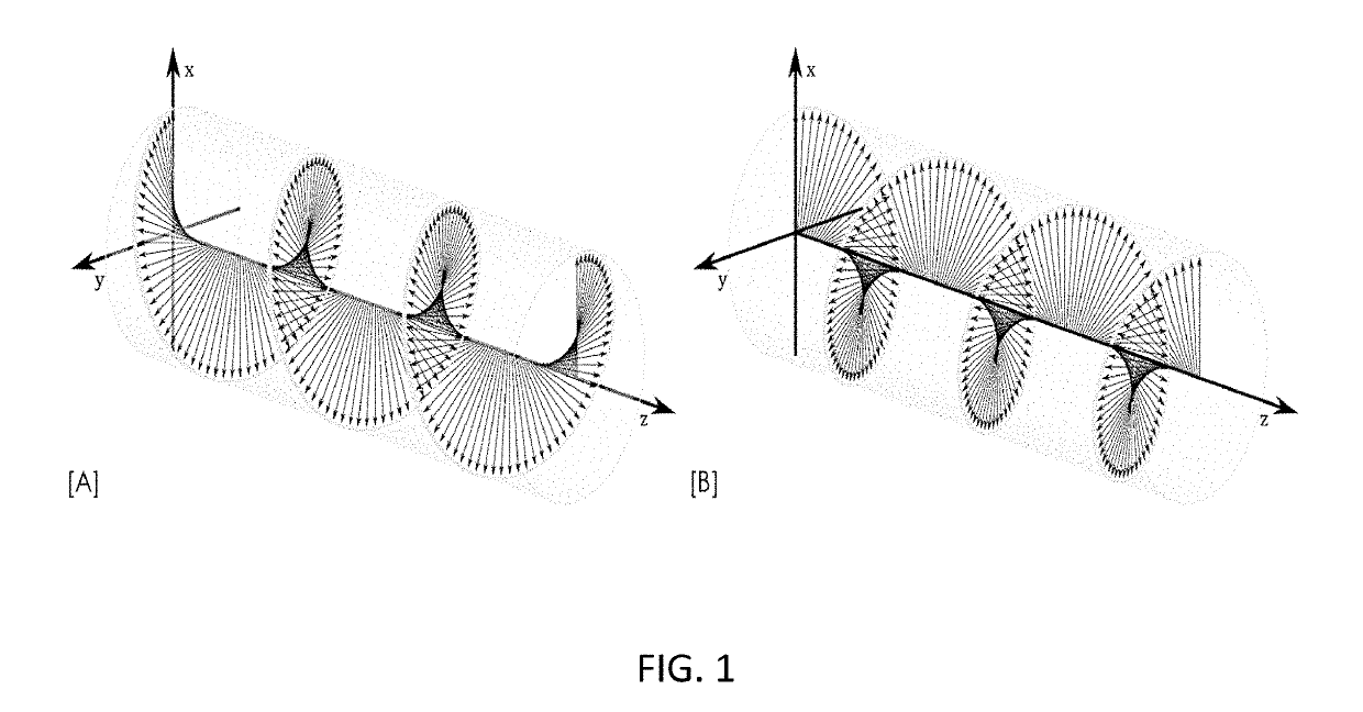
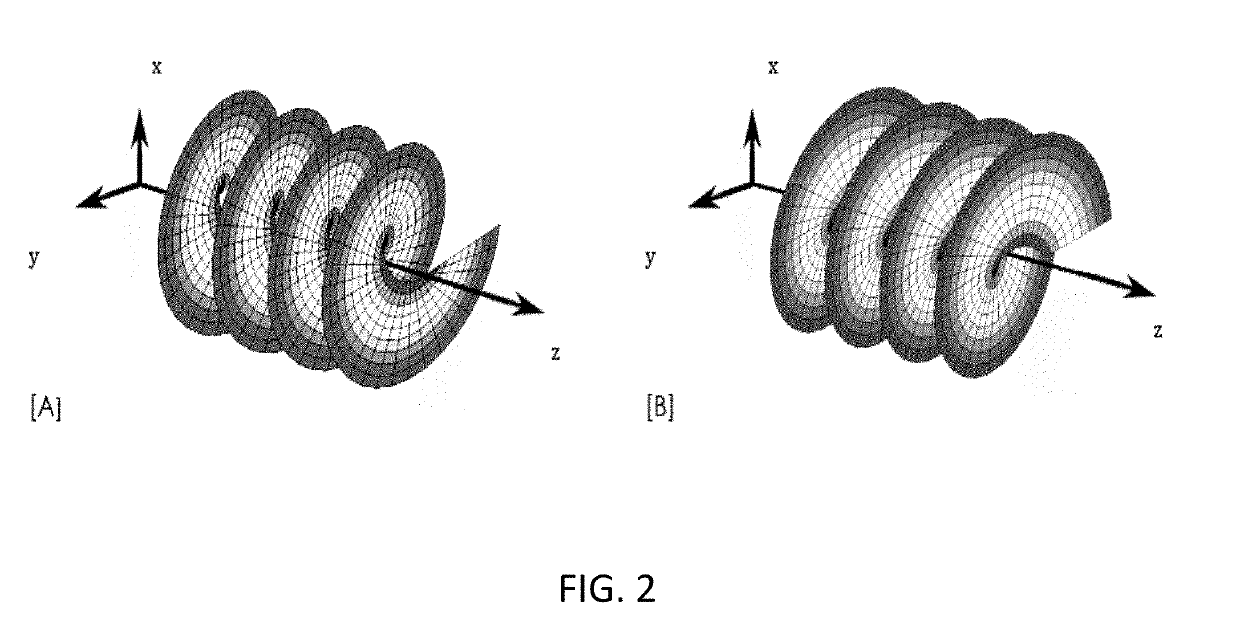
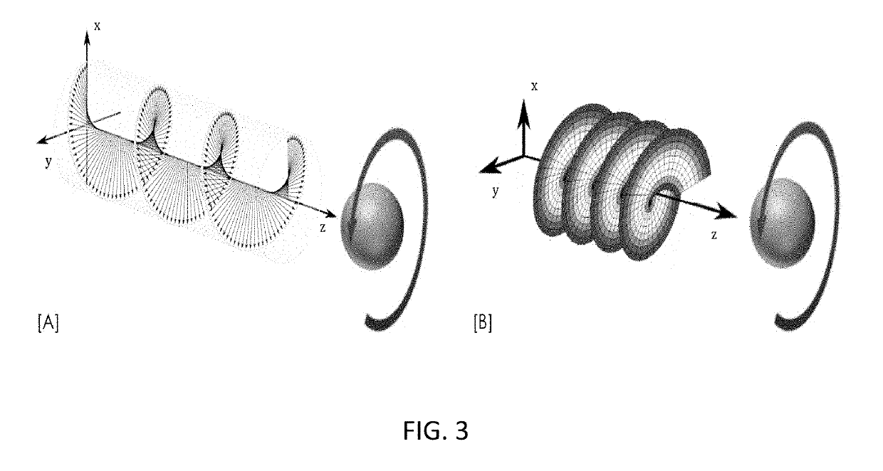
[0074]Referring now specifically to FIG. 4, one representation of the invention is an apparatus [A], [B] comprising a source of UV photons [1], one or more stand alone angular momentum generators [2] configured to deliver UV photons with optimized spin angular momentum (SAM), org orbital angular momentum (OAM), and / or a SAM / OAM [3] combination to target organic or inorganic substance and / or impurity. The angular momentum generator can have different forms [a], [b], [c], and [d].

[0075]Referring now specifically to FIG. 4 [2a], UV photons can acquire optimized OAM with a Spiral Phase Plate made of UV transparent material with refractive index 17, having an inhomogeneous thickness, h proportional to the azimuthal angle Φ

h=hsφ2π+h0

where hs is the step height, and h0 is the base height. When a beam of electromagnetic radiation (Gaussian) with plane phase distribution passes through this OAM generator, an optical vortex charge q is imprinted according to

q=hs(n-n0)λ

[0076]This means that th...


PUM

PropertyMeasurementUnit
Transparencyaaaaaaaaaa
Resolution enthalpyaaaaaaaaaa
Angular momentumaaaaaaaaaa

Abstract

A system for transferring near-UV and/or UV photons with engineered angular momentum on to matter, and treat organic and inorganic substances and/or impurities comprising a coherent or incoherent source of near-UV and/or UV photons, and one or more angular momentum generators configured to deliver near-UV and/or UV photons with optimized spin angular momentum (SAM), orbital angular momentum OAM, and/or a SAM/OAM combination to target organic or inorganic substance and/or impurity, wherein the angular momentum generators are scalable such that they can be fabricated as a stand alone structure, as a structure fabricated on the package of the near-UV and/or UV photon source, or as an integral part of the near-UV and/or UV photon source.

Description

CROSS-REFERENCE TO RELATED APPLICATION[0001]The present patent application / patent claims the benefit of priority of co-pending U.S. Provisional Patent Application No. 62 / 612,771, filed on Jan. 2, 2018, and entitled “SYSTEM AND METHOD FOR ENHANCED TREATING OF MATTER WITH ENGINEERED ANGULAR MOMENTUM UV PHOTONS,” and U.S. Provisional Patent Application No. 62 / 613,794, filed on Jan. 5, 2018, and entitled “SYSTEM AND METHOD FOR ENHANCED STEREOLITHOGRAPHY 3D PRINTING,” the contents of both of which are incorporated in full by reference herein.STATEMENT OF GOVERNMENT SUPPORT[0002]The present invention was made with U.S. Government support pursuant to Award No. 140D6318C0009 by the Defense Advanced Research Projects Agency (DARPA). Accordingly, the U.S. Government may have certain rights herein.FIELD OF THE INVENTION[0003]The present invention relates generally to systems and methods for treating compressible and non-compressible fluids, surfaces, and materials with photons of electromagnet...

Claims


Application Information

Patent Timeline
IPC IPC(8): G02B5/18G02B5/32
CPCG02B5/1838G02B5/32B33Y10/00B29C64/135B29C64/264B33Y30/00B29C64/268B29C64/277B29C64/393B29C64/286
Inventor BATONI, PAOLO
Owner NUSPOT TECH LLC
Why Eureka
Try Eureka