Method and device for operating a braking system, and braking system

Inactive Publication Date: 2019-07-18
ROBERT BOSCH GMBH
View PDF8 Cites 1 Cited by
  • Summary
  • Abstract
  • Description
  • Claims
  • Application Information

AI Technical Summary

Benefits of technology

[0004]The method according to the present invention, having the features described herein, has the advantage that the brake pedal unit is monitored for the nature of the actuation of the brake pedal, and the limitation of the operating current is canceled if a highly dynamic actuation is detected. The method according to the present invention has the advantage that the setpoint braking torque is made available to the driver within a short period of time in the event of highly dynamic braking operations, it nevertheless being ensured that overhe

Problems solved by technology

It is assumed here that highly dynamic braking operations increas

Method used


Image

  • Method and device for operating a braking system, and braking system
  • Method and device for operating a braking system, and braking system
  • Method and device for operating a braking system, and braking system

Examples


Embodiment Construction

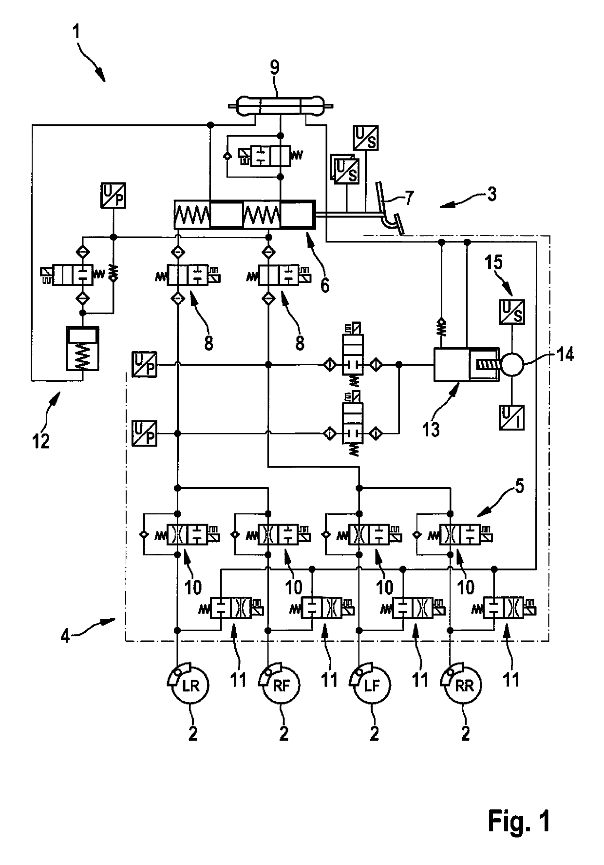
[0017]FIG. 1 shows, in a simplified diagram, a braking system 1 for a motor vehicle (not shown in greater detail here). Braking system 1 includes multiple wheel brakes 2, which may be actuated as service brakes by a driver of the motor vehicle by way of a brake pedal unit 3. Wheel brakes 2 are denoted by LR, RF, LF and RR, which explains their position or assignment on the motor vehicle, where LR stands for left rear, RF for right front, LF for left front and RR for right rear. Two brake circuits 4 and 5 are formed between brake pedal unit 3 and wheel brakes 2, brake circuit 4 being assigned to wheel brakes LF and RR and brake circuit 5 being assigned to wheel brakes LR and RF. The two brake circuits 4 and 5 are of identical construction, and therefore the construction of both brake circuits 4, 5 will be explained in greater detail below on the basis of brake circuit 4.

[0018]Brake circuit 4 is initially connected to a master brake cylinder 6 of brake pedal unit 3, master brake cylin...


PUM


Abstract

A method for operating a hydraulic braking system of a motor vehicle, including at least one hydraulically actuatable wheel brake, a brake pedal unit including an actuatable brake pedal for predefining a setpoint braking torque, and a pressure generator which is electrically actuated in order to generate a hydraulic pressure as a function of the setpoint braking torque, an electrical operating current of the pressure generator being limited to a first predefinable limiting value during normal operation. The brake pedal unit is monitored for the nature of actuation of the brake pedal, and the limitation of the operating current is canceled if highly dynamic actuation of the brake pedal is detected.

Description

FIELD OF THE INVENTION[0001]The present invention relates to a method for operating a hydraulic braking system of a motor vehicle, including at least one hydraulically actuatable wheel brake, a brake pedal unit including an actuatable brake pedal for predefining a setpoint braking torque, and a pressure generator which is electrically actuated in order to generate a hydraulic pressure as a function of the setpoint braking torque, an electrical operating current of the pressure generator being limited to a first predefinable limiting value during normal operation. The present invention also relates to a device for carrying out the described method, and to a braking system including such a device.BACKGROUND INFORMATION[0002]Methods, devices and braking systems of the type mentioned at the outset are believed to be understood from the related art. While in conventional braking systems a vacuum brake booster in the brake pedal unit is used to boost the braking force exerted by the drive...

Claims


Application Information

Patent Timeline
IPC IPC(8): B60T8/32B60T17/22B60T7/04B60T8/17B60T8/171B60T13/20B60T13/66
CPCB60T8/326B60T17/22B60T7/042B60T8/17B60T8/171B60T13/20B60T13/66B60T2250/00B60T2270/82B60T8/3275B60T8/4072B60T8/4081B60T13/662B60T13/745B60T2201/03B60T13/146B60T13/686
Inventor BRESSER, ANDREAS
Owner ROBERT BOSCH GMBH
Why Eureka
Try Eureka