
Method and apparatus for monitoring, detecting, testing, diagnosing and/or mitigating interference in a communication system

a communication system and method and apparatus technology, applied in the field of method and apparatus for monitoring, detecting, testing, diagnosing and/or mitigating interference in a communication system, can solve problems such as sc-1-dma being very susceptible to interference, affecting the performance of an entire lte cell, and introducing problems with sc-fdma

Active Publication Date: 2019-07-18
ILLINOIS SUPERCONDUCTOR CORP
View PDF24 Cites 73 Cited by
  • Summary
  • Abstract
  • Description
  • Claims
  • Application Information

AI Technical Summary

Benefits of technology

The patent text describes a method and apparatus for detecting, measuring, and mitigating interference in a communication system. The technical effects of this patent include improving the detection and mitigation of interference in LTE networks, which can improve the performance and reliability of mobile communication devices. The method and apparatus can also be used in other communication systems, such as CDMA, to detect and mitigate interference.

Problems solved by technology

However, the use of SC-FDMA also introduces problems.
SC-1-DMA is very susceptible to interference.
Even a small amount of interference can degrade the performance of an entire LTE cell.
A leading source of interference impacting LTE networks is passive intermodulation (PIM) interference.
PIM occurs when RF energy from two or more transmitters is non-linearly mixed in a passive circuit, such as bad RF connections, damaged cables, poor antennas or reflections from objects such as buildings.
PIM becomes interference to a cellular base-station when one of the intermodulation products interferes with base-station receive channels (LTE uplink) that are utilized by mobile or stationary communication devices.
In most communication environments involving short range or long range wireless communications, interference from unexpected wireless sources can impact the performance of a communication system leading to lower throughput, dropped calls, reduced bandwidth which can cause traffic congestion, or other adverse effects, which are undesirable.

Method used


Image

  • Method and apparatus for monitoring, detecting, testing, diagnosing and/or mitigating interference in a communication system
  • Method and apparatus for monitoring, detecting, testing, diagnosing and/or mitigating interference in a communication system
  • Method and apparatus for monitoring, detecting, testing, diagnosing and/or mitigating interference in a communication system

Examples


Embodiment Construction

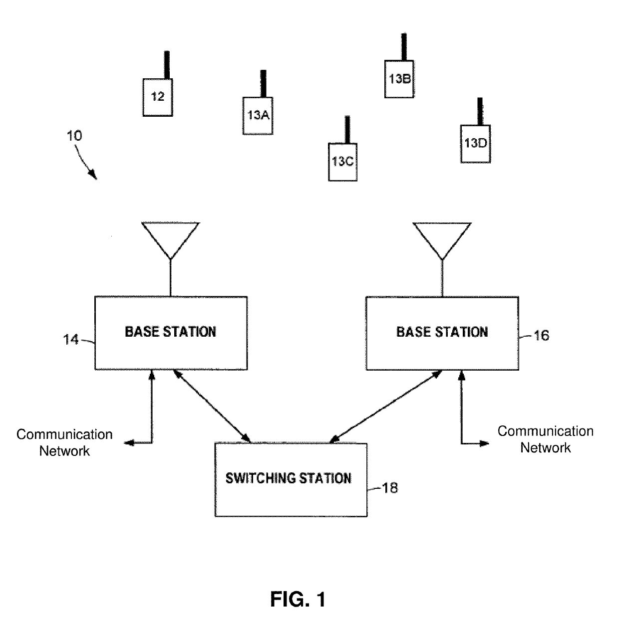
[0049]The subject disclosure describes, among other things, illustrative embodiments for monitoring, detecting, testing, diagnosing and / or mitigating interference. Other embodiments are included in the subject disclosure.

[0050]One embodiment of the subject disclosure includes a method with steps including receiving, by a first base station, a wireless signal, wherein the wireless signal corresponds to an uplink signal; converting, by the first base station, the wireless signal to a CPRI signal; and determining, by the first base station, from the CPRI signal, whether there is a presence of first interference caused by a downlink signal that mixes with the uplink signal, second interference caused by uplink noise generating by user equipment communicating with a second base station, third interference caused by noise caused by a defective transmission from the second base station, fourth interference caused by noise caused by one or more adjacent base stations not including the first...


PUM


Abstract

A system that incorporates aspects of the subject disclosure may perform operations including, for example, receiving, via an antenna, a signal generated by a communication device, detecting passive intermodulation interference in the signal, the interference generated by one or more transmitters unassociated with the communication device, and the interference determined from signal characteristics associated with a signaling protocol used by the one or more transmitters. Other embodiments are disclosed.

Description

CROSS-REFERENCE TO RELATED APPLICATION(S)[0001]This application is a continuation of U.S. application Ser. No. 16 / 054,531, filed Aug. 3, 2018, which claims the benefit of U.S. Provisional Application No. 62 / 543,208, filed Aug. 9, 2017, and U.S. Provisional Application No. 62 / 545,688, filed Aug. 15, 2017, all of which are incorporated herein by reference in their entirety.FIELD OF THE DISCLOSURE[0002]The subject disclosure is related to a method and apparatus for monitoring, detecting, testing, diagnosing and / or mitigating interference in a communication system.BACKGROUND OF THE DISCLOSURE[0003]Fourth-Generation Long Term Evolution (LTE) downlink signals are modulated using orthogonal-frequency domain multiplexing (OFDM). The LTE uplink, on the other hand, uses single-carrier frequency domain multiple access (SC-1-DMA). SC-FDMA was selected for the LTE uplink because it has a much lower peak-to-average than OFDM, and therefore, it helps reduce the power consumption of mobile phones. ...

Claims


Application Information

Patent Timeline
Patent Type & Authority Applications(United States)
IPC IPC(8): H04B17/336H04W24/10H04B1/71H04L27/26H04B17/18H04B1/10H04L25/08H04J11/00H04B1/715H04B1/711H04B1/04H04L25/03H04W72/08H04W24/08
CPCH04B17/336H04W24/10H04B1/71H04L27/2647H04B17/18H04B1/1036H04L25/08H04J11/0063H04J11/0026H04B1/715H04B1/711H04B1/0475H04L25/03821H04L27/2691H04W72/082H04W24/08H04B2001/1045H04B17/318H04L27/2623H04B1/7087H04J11/0023H04W72/541
Inventor ABDELMONEM, AMR
Owner ILLINOIS SUPERCONDUCTOR CORP
Learn More