Apparatus and A Method For Inspecting A Light Transmissible Optical Component

a technology of optical components and apparatuses, applied in the field of inspection of light transmissible optical components, can solve the problems of difficult inspection of optical lenses for defects, high time-consuming and laborious process, and not all of these defects are readily identifiable through visual inspection

Active Publication Date: 2019-07-25
HONG KONG APPLIED SCI & TECH RES INST
View PDF25 Cites 7 Cited by
  • Summary
  • Abstract
  • Description
  • Claims
  • Application Information

AI Technical Summary

Benefits of technology

[0007]Another object of the present invention is to mitigate or obviate to some degree one or more problems associated with known means for inspecting light transmissible optical components, or at least to provide a useful alternative.

Problems solved by technology

Very often, these optical instruments or their variations comprise one or more light transmissible optical components such as optical lenses, and, during their manufacturing process, inspection of these optical lenses for defects has always been challenging.
Lens inspection generally requires specialized skills of the human inspector, and the process can be highly time consuming and labor intensive.
Existing methods of inspection may involve manual and visual checking for defects at the lens such as black spots, scratches, white dots, dust or dirt particles, air bubbles, digs, smudges, flow marks and / or other injection or coating defects, but not all of these defects are readily identifiable through visual checking alone.
Quality of such inspections is thus largely dependent on the judgement and experience of the inspecting individual, which could be subjective and inconsistent.
Accuracy of the inspections may further be compromised, especially during a mass production process, where a large number of lenses are to be manually and visually inspected quickly.
It would be understandable that continuous and repetitive visual checking for long hours may cause vision fatigue or even damage to one's eyesight, which may further deteriorate quality and reliability of the inspection process.
This method requires a reference image for comparison to identify defects in a target image, but the production of suitable reference images can lead to the identification of false defects in target images.

Method used


Image

  • Apparatus and A Method For Inspecting A Light Transmissible Optical Component
  • Apparatus and A Method For Inspecting A Light Transmissible Optical Component
  • Apparatus and A Method For Inspecting A Light Transmissible Optical Component

Examples


first embodiment

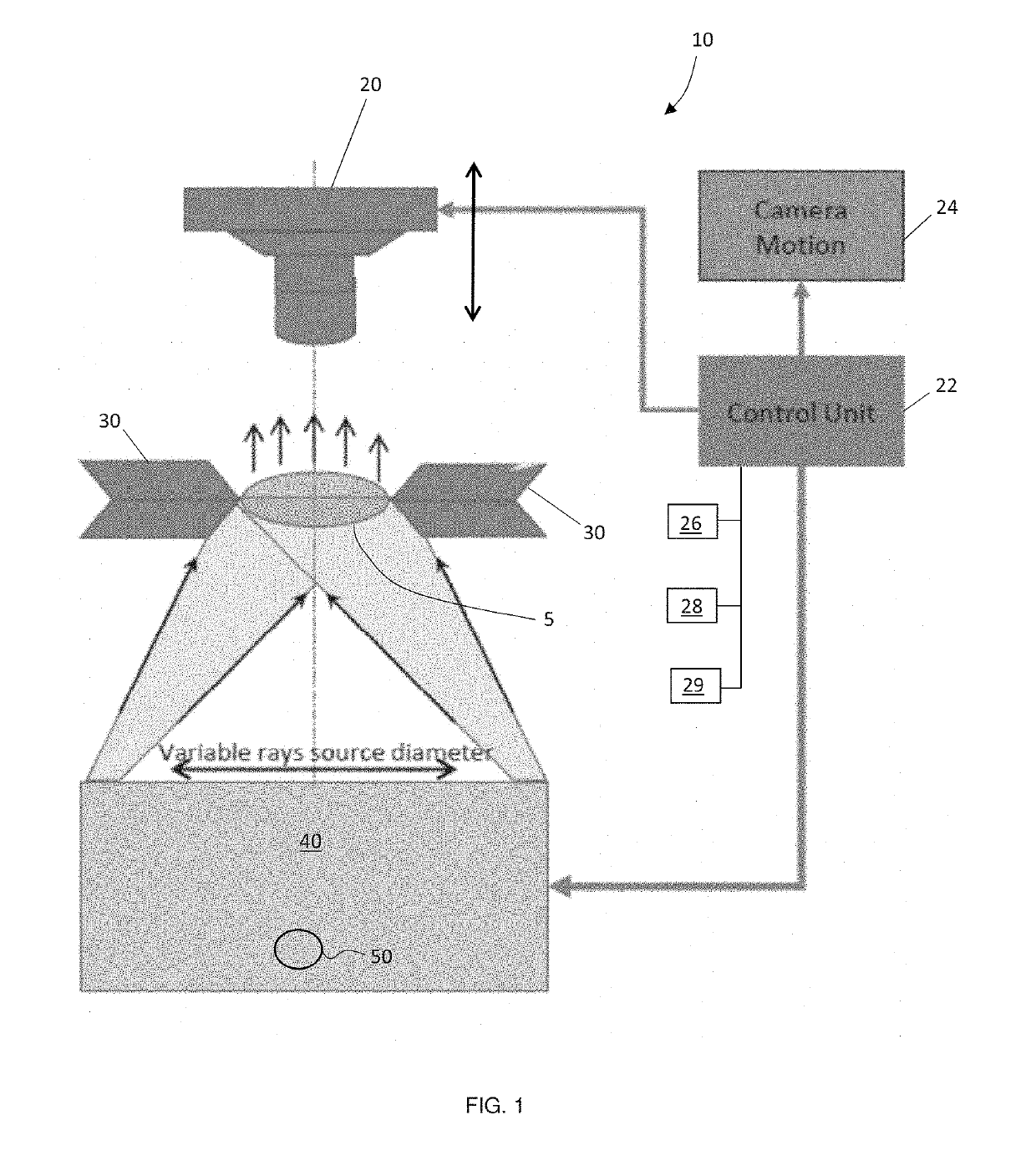
[0038]Referring to FIG. 1, shown is a schematic diagram of the apparatus 10 for inspecting a light transmissible optical component 5 according to the present invention. The optical component 5 can be any light transmissible object for various purposes such as, but not limited to, optical lenses for use in cameras, camera phones, video recorders, monoculars or binoculars, telescopes, or microscopes. The optical lenses may also be formed of any suitable materials which allow light transmission such as but not limited to crystals, glasses or plastics, etc. In the context of the present application, the term “light transmissible optical component” is not limited to transparent optical components, but includes, by way of example only, opaque optical components which do not transmit therethrough the whole of the light spectrum incident on a surface thereof. It also includes optical components having an anti-reflective surface or coating where the anti-reflective surface or coating is desi...

second embodiment

[0063]FIG. 6 is a schematic diagram showing the apparatus for inspecting a light transmissible optical component according to the present invention. Like numerals to depict like parts shown in FIG. 1 are denoted by the same numerals, but preceded by a “2”.

[0064]The apparatus 210 differs from the apparatus of FIG. 1 in that the illumination device 240 is positioned on a same first side of the light transmissible optical component 205 held by the support 230 as that of the image capturing module 220. As in other embodiments, the apparatus 210 may be automatically controlled by the control unit 222. A further difference is the provision of an optical element or beam splitter 260 positioned between the image capturing module 220 and the support 230. The optical element or beam splitter 260 is arranged to redirect shaped light from the illumination device 240 towards the light transmissible optical component 205 under inspection and to allow shaped light reflected by a surface of the lig...

third embodiment

[0067]FIG. 7 is a schematic diagram showing the apparatus for inspecting a light transmissible optical component according to the present invention. Like numerals to depict like parts shown in FIG. 1 are denoted by the same numerals, but preceded by a “3”.

[0068]The apparatus 310 is generally the same as the apparatus of FIG. 6 save for the inclusion in the apparatus 310 of one or more additional illuminators 370 preferably positioned adjacent to the support 330 on a same side as the image capturing module 330, although in some arrangements, the additional illuminators 370 may be positioned on an opposite (lower) side of the support 330 or on both sides of the support 330.

[0069]The illumination device 340 and the one or more additional illuminators 370 may be configured to be selectively switched on to enable the image capturing module 320 to capture one or more bright field images and / or dark field images of the optical component 305 being inspected for various configurations of ill...


PUM

PropertyMeasurementUnit
incident anglesaaaaaaaaaa
diameteraaaaaaaaaa
focal lengthaaaaaaaaaa

Abstract

The invention provides an apparatus for inspecting a light transmissible optical component. The apparatus comprises an image capturing module arranged on a first side of a support configured to hold a light transmissible optical component whilst it is being inspected. The apparatus includes an illumination device configured to shape light from a light source and to illuminate a selected portion of a surface of said light transmissible optical component with said shaped light to enable the image capturing module to capture any of a bright field image, a dark field image, or a combined bright field and dark field image of the light transmissible optical component being held by the support.

Description

FIELD OF THE INVENTION[0001]The invention relates to the field of inspecting light transmissible optical components and, particularly, but not exclusively, to an apparatus and a method for inspecting defects including anti-reflective coating defects in light transmissible optical components such as optical lenses.BACKGROUND OF THE INVENTION[0002]Optical instruments such as cameras and / or video cameras have been so commonly used in daily life that variations of them have been widely incorporated into portable electronic devices such as smart phones, tablet computers, as well as mobile surveillance units such as digital image and / or video recorders for home use or installed in vehicles or in buildings. Very often, these optical instruments or their variations comprise one or more light transmissible optical components such as optical lenses, and, during their manufacturing process, inspection of these optical lenses for defects has always been challenging. Lens inspection generally re...

Claims


Application Information

Patent Timeline
Patent Type & Authority Applications(United States)
IPC IPC(8): G01N21/88G01N21/958
CPCG01N21/8806G01N21/958G01N2021/8825G01N2021/8835G01N2021/9583G01N2201/0675G01N2021/8845
Inventor NITIKIN, VLADISLAVNG, WANG FEIWONG, KA KITREN, XIAOZHELIU, YING
Owner HONG KONG APPLIED SCI & TECH RES INST
Why Eureka
Try Eureka