
Electrical building block

a technology of building blocks and building blocks, applied in the direction of electrical equipment, toys, coupling device connections, etc., can solve the problems of limited assembling process of commercially available building blocks, design that is detrimental to overall space utilization and style flexibility, and large increase in cost of using building blocks, so as to improve the application of electrical connection mechanisms with different docking specifications

Inactive Publication Date: 2019-08-01
EAGLE TECH
View PDF45 Cites 9 Cited by
  • Summary
  • Abstract
  • Description
  • Claims
  • Application Information

AI Technical Summary

Benefits of technology

This patent is for an electrical building block that has magnets or magnetic buckles on its sides to improve stability when connecting electrical components. The technical effect of this design is to make the electrical building block more reliable and stable when in use.

Problems solved by technology

That is, the assembling process of the commercially available building blocks is limited by the locations and the direction of the electrical connection mechanism.
In other words, this design is detrimental to the overall space utilization and the style flexibility.
In case that the assembling requirements of the overall electrical building block product are taken into consideration, plural electrical building blocks of the same type are required because the assembling process of the commercially available building blocks is limited by the locations and the directions of the electrical connection mechanism.
Consequently, the cost of using the building blocks is largely increased.
Moreover, the conventional building blocks still have some other drawbacks.
That is, the docking flexibility of the electrical building block is restricted.
Moreover, since the number of the function modules is increased and the design is unsatisfactory, many components are exposed outside.
Under this circumstance, the conventional electrical building blocks are not aesthetically pleasing and the danger of using the electrical building blocks is increased.

Method used


Image

  • Electrical building block
  • Electrical building block
  • Electrical building block

Examples


first embodiment

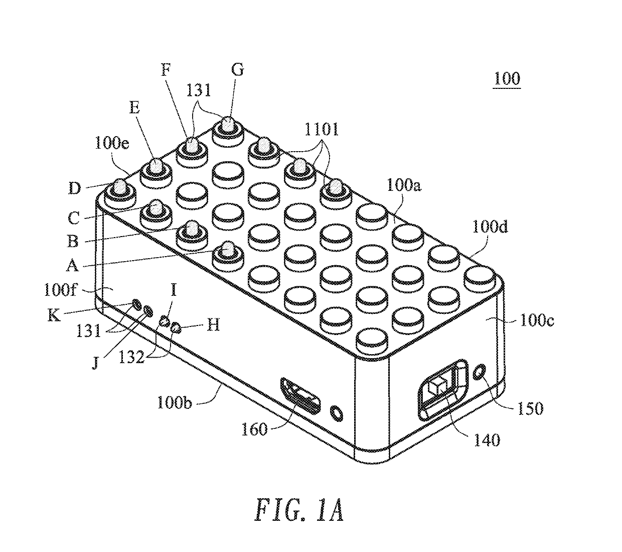
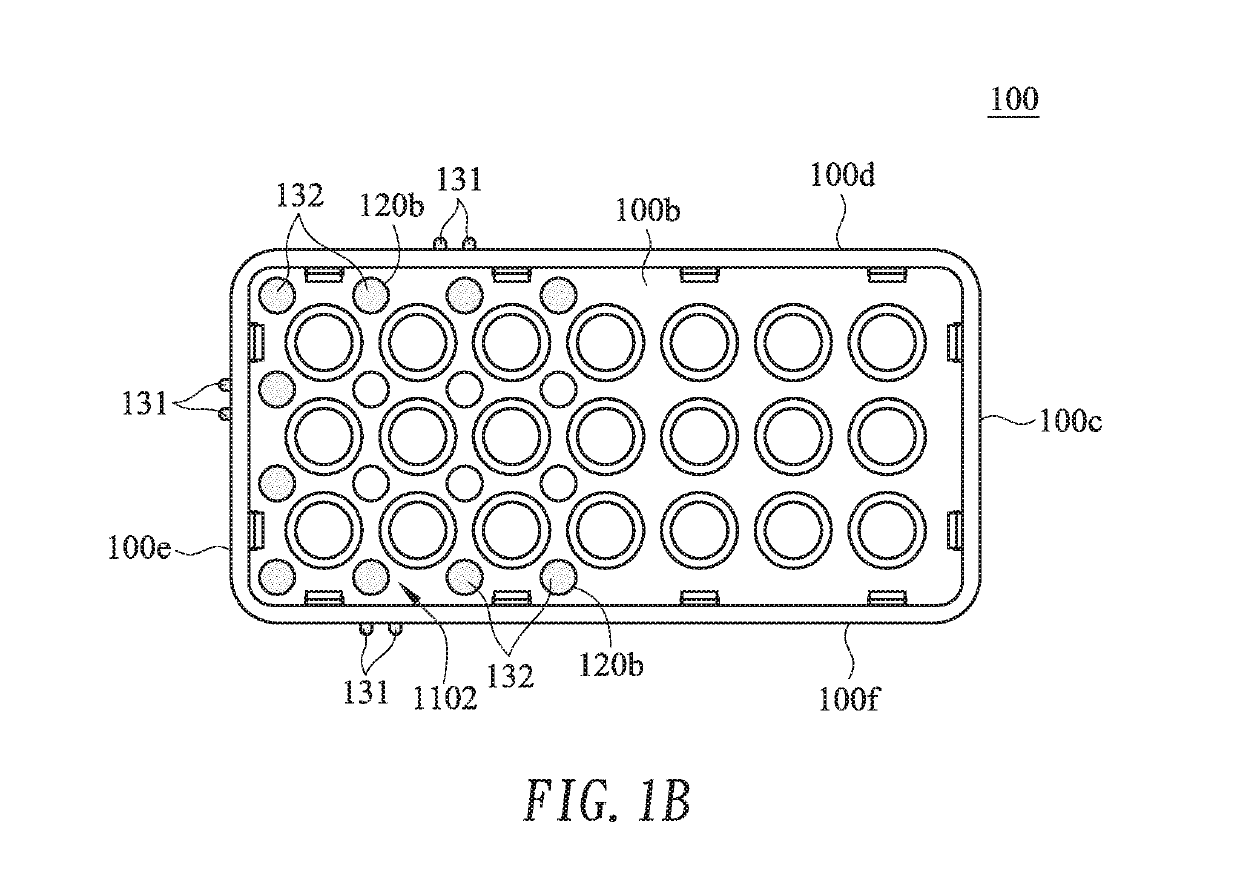
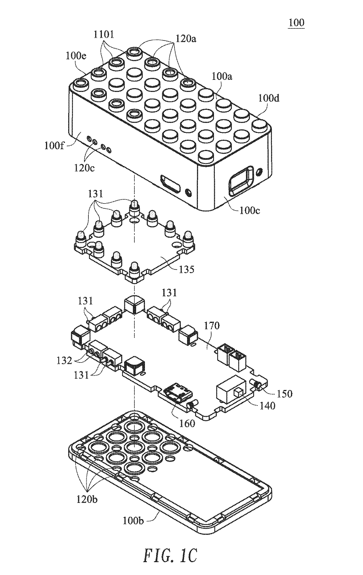
[0073]FIGS. 1A to 1E are schematic perspective view, bottom view and exploded view illustrating the concepts according to the present invention.

[0074]The present invention provides an electrical building block. The electrical building block of the present invention also retains the docking structure to be assembled with the general building block such as a LEGO building block. For example, the commercially available LEGO building block usually has the size from 1×1 cm to 48×48 cm. According to the technology of the present invention, the electrical connection mechanisms for connecting plural electrical building blocks are improved. The electrical connection mechanisms include a first electrical connection mechanism and a second electrical connection mechanism. Hereinafter, the combination and application of the two electrical connection mechanisms with different docking specifications will be illustrated by taking a power-storage building block of the electrical building block as an...

third embodiment

[0106]FIG. 2C is a schematic perspective view illustrating the concepts of the present invention. In this embodiment, the electrical building block 201 comprises a top side 201a, a bottom side 201b, plural lateral sides 201c, 201d, 201e, 201f, plural top-side docking structures 2011, plural bottom-side docking structures (not shown), plural first openings 2012a, plural second openings (not shown), plural third openings 2012c, a first electrical connection mechanism with plural first electrical contact structures 20131, a second electrical connection mechanism with plural second electrical contact structure 20132, and a switch element 2014.

[0107]In comparison with the above embodiment, the electrical building block 201 is an adjustable resistor building block. Moreover, the switch as shown in FIGS. 2A and 2B is replaced with an adjustable resistor switch 2014, which is also an electrical functional module. By rotating the adjustable resistor switch 2014 of the adjustable resistor bui...

seventh embodiment

[0117]FIG. 6A is schematic perspective view illustrating the concepts according to the present invention. FIG. 6B is a partial enlarged view illustrating the concepts as shown in FIG. 6A. In FIG. 6A and FIG. 6B, a cord-type electrical building block 600 is provided. In this embodiment, the cord-type electrical building block 600 complies with a single docking specification. The cord-type electrical building block 600 comprises a block body 610, a top side 610a, bottom side 610b, plural top-side docking structures 6201, plural bottom-side docking structures 6202, plural second openings 630b, a second electrical connection mechanism with plural second electrical contact structures 642 (e.g., female connectors) and an extension cord 650. The extension cord 650 is also an electrical function module. A first part and a second part of the block body 610 are located at two ends of the cord-type electrical building block 600, respectively. The first part and the second part of the block bod...


PUM


Abstract

An electrical building block includes docking structures, a first electrical connection mechanism, a second electrical connection mechanism and a circuit board. The docking structures are located at a top side of the electrical building block. The first electrical connection mechanism and the second electrical connection mechanism are electrically connected with the circuit board and disposed within the electrical building block. The first electrical connection mechanism is penetrated through the top side and elastically protruded out of the docking structures. The second electrical connection mechanism is located at a bottom side of the electrical building block. The second electrical connection mechanism of the electrical building block is docked with the first electrical connection mechanism of an adjacent electrical building block. Moreover, the two electrical connection mechanisms are formed on at least one lateral side of the electrical building block to be connected with another adjacent electrical building block.

Description

CROSS-REFERENCE TO RELATED APPLICATION[0001]This application claims priority to U.S. Provisional Patent Application No. 62 / 623,053 filed Jan. 29, 2018, the contents of which are incorporated herein by reference.FIELD OF THE INVENTION[0002]The present invention relates to an electrical building block, and more particularly to an electrical building block with two types of electrical connection mechanisms on at least one lateral side, so that plural electrical building blocks can be electrically connected with each other in diverse directions.BACKGROUND OF THE INVENTION[0003]In the early stage, the building block is one kind of plastic toy. Each building block can be closely engaged with another building block, and plural building blocks are assembled into a specified shape, for example a car or a house. Consequently, the uses of the building blocks can facilitate the growth of the child's brain and stimulate the imagination space of the child.[0004]Due to the increasingly fine design...

Claims


Application Information

Patent Timeline
IPC IPC(8): A63H33/08A63H33/04H01R13/514
CPCH01R13/514A63H33/086A63H33/042A63H33/26H01R9/2408
Inventor LIN, WEI-CHENLEE, CHUNG-IYANG, CHIEN-YING
Owner EAGLE TECH
Learn More