Acceleration and deceleration control system and acceleration and deceleration control method

a control system and acceleration technology, applied in the direction of braking system, using reradiation, instruments, etc., can solve problems such as excessive unease of occupants

Active Publication Date: 2019-08-01
DENSO CORP
View PDF0 Cites 5 Cited by
  • Summary
  • Abstract
  • Description
  • Claims
  • Application Information

AI Technical Summary

Benefits of technology

[0005]As set forth above, the acceleration and deceleration system of PTL 1 is configured such that an excessive lateral centrifugal force is less likely to act on the occupant of the own vehicle due to use of the preset lateral acceleration. Moreover, this acc

Problems solved by technology

However, as a result of elaborate researches and studies of the inventors, the following issue has been found.
Specifically, since the position of the own vehicle changes three-dimensionally in relation to the actual road profile, mere

Method used


Image

  • Acceleration and deceleration control system and acceleration and deceleration control method
  • Acceleration and deceleration control system and acceleration and deceleration control method
  • Acceleration and deceleration control system and acceleration and deceleration control method

Examples


first embodiment

1. First Embodiment

(1-1. Overall Configuration)

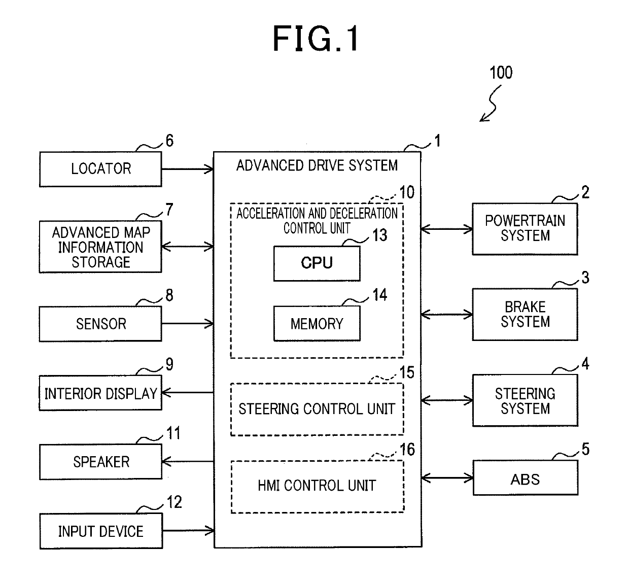
[0025]As shown in FIG. 1, a vehicle 100 includes an advanced drive system 1 which includes an acceleration and deceleration control unit 10 for controlling acceleration and deceleration of the own vehicle. The advanced drive system 1 corresponds to an acceleration deceleration control system.

[0026]The vehicle 100 includes various control systems, such as a powertrain system 2, a brake system 3, a steering system 4, and an antilock braking system 5 (hereinafter referred to as the ABS 5). These control systems 2 to 5 and the advanced drive system 1 are connected to an in-vehicle local network (hereinafter referred to as the in-vehicle LAN), not shown. These control systems 2 to 5 and the advanced drive system 1 are configured to share control information, such as control command or controlled variable, through communication via the in-vehicle LAN.

[0027]The advanced drive system 1, when activated, performs acceleration and deceleration con...

second embodiment

2. Second Embodiment

2-1. Differences from the First Embodiment

[0099]The basic configuration of the second embodiment is similar to that of the first embodiment. Therefore, the following description is focused on the differences from the first embodiment. The components similar to those of the first embodiment are given the same reference signs. For these components, previous description should be referred to.

[0100]In the first embodiment, the limit correction block 32 is configured to output the command for temporarily reducing the acceleration limit or the jerk limit, to the limit setting block 22. As shown in FIG. 10, the second embodiment is different from the first embodiment in that the limit correction block 32 outputs the command for temporarily reducing the drive command, to the command calculation block 25.

[0101]Specifically, it is so configured that, when restarting the output of the drive command that has been stopped by the output control of the override command block 31...


PUM


Abstract

A forward information acquisition unit acquires a road profile ahead of the own vehicle. A position acquisition unit acquires a current position of the own vehicle. A state acquisition unit acquires a current speed of the own vehicle. A command calculation unit calculates a target speed at each point on a road ahead of the own vehicle, based on the road profile and the current position, and calculates a drive command for driving the own vehicle in the longitudinal direction of the own vehicle, based on the target speed and the current speed. The road profile includes a road gradient. The command calculation unit is configured to adjust the drive command, based on variation in the road gradient and Gzmax that is an acceleration limit limiting acceleration of the own vehicle in the vertical direction.

Description

CROSS-REFERENCE TO RELATED APPLICATIONS[0001]This application is based on and claims the benefit of priority from earlier Japanese Patent Application No. 2016-175524 filed Sep. 8, 2016, all the description of which is incorporated herein by reference.TECHNICAL FIELD[0002]The present disclosure relates to a technique for controlling acceleration and deceleration of the own vehicle.BACKGROUND ART[0003]Techniques for controlling acceleration and deceleration of the own vehicle are well known. These techniques are applied to the system for controlling acceleration and deceleration of the own vehicle to appropriately obtain a deceleration region when approaching a curve, a constant speed region when traveling on the curve, and an acceleration region when departing from the curve.[0004]For example, PTL 1 describes an acceleration and deceleration control system that uses a turning radius at each node on a curve, and a preset lateral acceleration of the own vehicle to calculate a target sp...

Claims


Application Information

Patent Timeline
IPC IPC(8): B60W40/072B60W50/038G01S13/06B60W40/105
CPCB60W40/072B60W50/038G01S13/06B60W40/105B60T2230/04B60W2550/146B60W2550/402B60T7/12G08G1/16B60W2720/103B60W50/0097B60W30/143B60W2552/30B60W2555/20B60W2552/15B60W2556/50B60W40/076
Inventor WATANABE, DAIJIMATSUMOTO, TOSHIKIAKATSUKA, HISAYA
Owner DENSO CORP
Why Eureka
Try Eureka