Sheet Conveying Apparatus

Active Publication Date: 2019-08-01
BROTHER KOGYO KK
View PDF9 Cites 0 Cited by
  • Summary
  • Abstract
  • Description
  • Claims
  • Application Information

AI Technical Summary

Benefits of technology

[0010]According to this configuration, the coil springs, which rotatably support the driven rollers, include the right-handed (clockwise) twining coil spring and the left-handed (counterclockwise) twining coil spring. Accordingly, it is possible to suppress the driven rollers from being inclined in an identical direction, and it is possible to sup

Problems solved by technology

Therefore, for example, when an image is recorded on a printing surface of the sheet while conveying the sheet by the paper discharge roller and the driven rollers, it is feared that the lan

Method used


Image

  • Sheet Conveying Apparatus
  • Sheet Conveying Apparatus
  • Sheet Conveying Apparatus

Examples


first modified embodiment

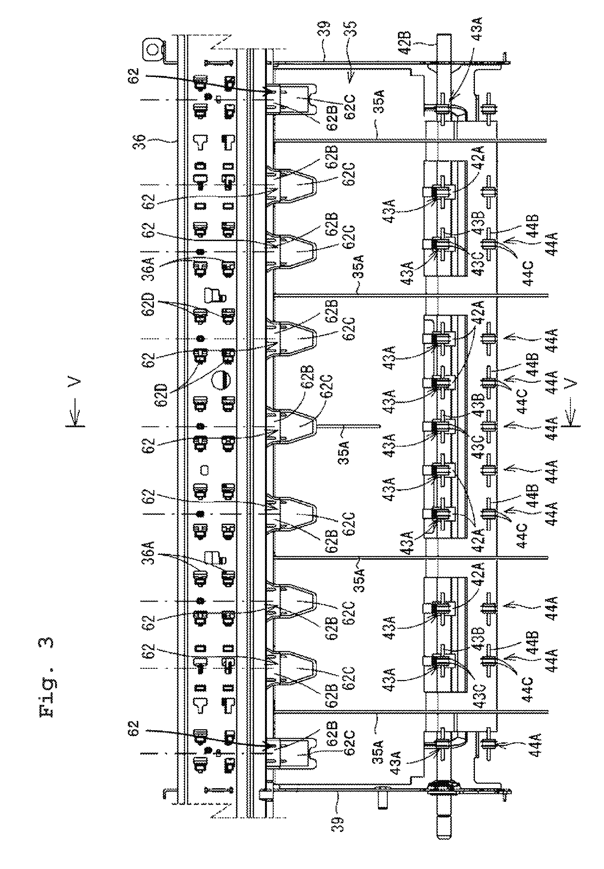
[0064]In the embodiment of the present teaching described above, the right-handed twining coil spring 43B1 and the left-handed twining coil spring 43B2 are alternately arranged in the width direction 9. However, there is no limitation to this construction. As depicted in FIG. 7, the following configuration is also appropriate. That is, the twining directions of the two coil springs 43B arranged on the outermost sides in the width direction 9 are different from each other in the area in which the recording paper 14 is conveyed. There is such a tendency that the recording paper 14 skews by being greatly affected by the force exerted from the first spur 43A arranged on the outer side in the width direction 9. Therefore, if the directions, in which the two first spurs 43A arranged on the both outer sides in the width direction 9 are inclined, are identical, the recording paper 14 more easily skews in the direction in which the first spurs 43A are inclined. In the first modified embodime...

second modified embodiment

[0066]A second modified embodiment will be explained with reference to FIG. 8. In the multifunction peripheral 10 of the embodiment described above, the recording paper 14 is conveyed in the state (center basis) in which the central portion in the width direction 9 moves along the central portion in the width direction 9 of the conveying passage 29. The center basis line O, which is assumed when the recording paper 14 is conveyed on the center basis as described above, is indicated by an alternate long and short dash line in FIG. 8. As depicted in FIG. 8, a guide member 29A is provided at the left end in the width direction 9 of the conveying passage 29, and a guide member 29B is provided at the right end in the width direction 9. The two guide members 29A, 29B are provided to guide the both ends in the width direction 9 of the recording paper 14, and they compart the conveying passage 29. The position of the center basis line O in the width direction 9 is the position which is sepa...

third modified embodiment

[0068]The spur support portion 46A of the third modified embodiment is different from that of the embodiment described above in that the spur support portion 46A is configured to retain the shaft member 43B while inclining the shaft member 43B with respect to the conveying direction 6. A detailed explanation will be made below with reference to FIGS. 9A and 9B.

[0069]A first regulating portion 72 of the spur support portion 46A is provided to interpose the shaft member 43B in the conveying direction 6. The first regulating portion 72 has a first regulating surface 72A and a second regulating surface 72B which are opposed to one another. Further, in the same manner as described above, a second regulating portion 73 is also provided to interpose the shaft member 43B in the conveying direction 6. The second regulating portion 73 has a third regulating surface 73A and a fourth regulating surface 73B which are opposed to one another. The four regulating surfaces has a role to regulate the...


PUM

PropertyMeasurementUnit
Widthaaaaaaaaaa
Areaaaaaaaaaaa

Abstract

A sheet conveying apparatus includes: a conveying roller configured to convey a sheet in a conveying direction; driven rollers arranged with intervals in a width direction intersecting with the conveying direction, the driven rollers being opposed to the conveying roller in a direction perpendicular to the conveying direction and the width direction; and coil springs provided corresponding to the driven rollers respectively and serving as rotating shafts for rotatably supporting the driven rollers, wherein the coil springs include a right-handed twining coil spring and a left-handed twining coil spring.

Description

CROSS REFERENCE TO RELATED APPLICATION[0001]The present application claims priority from Japanese Patent Application No. 2018-014577 filed on Jan. 31, 2018, the disclosure of which is incorporated herein by reference in its entirety.BACKGROUNDField of the Invention[0002]The present invention relates to a sheet conveying apparatus. In particular, the present invention relates to a structure which is useful to reduce a sheet skew caused by inclination of driven rollers with respect to a conveying direction of a sheet when the sheet is conveyed by a conveying roller and the driven rollers.Description of the Related Art[0003]As described in Japanese Patent Application Laid-open No. 2016-160025, a conventional ink-jet type printer generally adopts a structure which is provided with a paper discharge roller in order to convey a sheet in a subsidiary scanning direction. Further, driven rollers are provided at positions opposed to the paper discharge roller in order to convey the sheet in c...

Claims


Application Information

Patent Timeline
IPC IPC(8): B65H5/06
CPCB65H5/062B65H2404/12B65H29/125B65H2404/1431B65H2404/1345B65H2404/611B65H2404/54B65H2801/12B65H29/70B65H2301/5122B65H2404/1416B65H2404/1115B65H2801/15B65H2801/06B65H2402/54B65H2404/1341
Inventor MIMOTO, MASAOICHIKAWA, SHOHEINODA, KENGOITO, TSUYOSHITANIGUCHI, YOSHIMITSU
Owner BROTHER KOGYO KK
Why Eureka
Try Eureka