Centrifugal multiblade blower

Active Publication Date: 2016-10-20
DENSO CORP
View PDF2 Cites 4 Cited by
  • Summary
  • Abstract
  • Description
  • Claims
  • Application Information

AI Technical Summary

Benefits of technology

[0012]Accordingly, the total surface area is increased to be larger than the imaginary smooth surface. Therefore, it is possible to catch more copper powder flowing from the electric motor by the main plate o

Problems solved by technology

It is well-known that resin material and rubber material deteriorate if in contact with metal, in particular, copper.
The copper harm will be generated if copper powder flowing out of the blower as mentioned above adheres to res

Method used


Image

  • Centrifugal multiblade blower
  • Centrifugal multiblade blower
  • Centrifugal multiblade blower

Examples


first embodiment

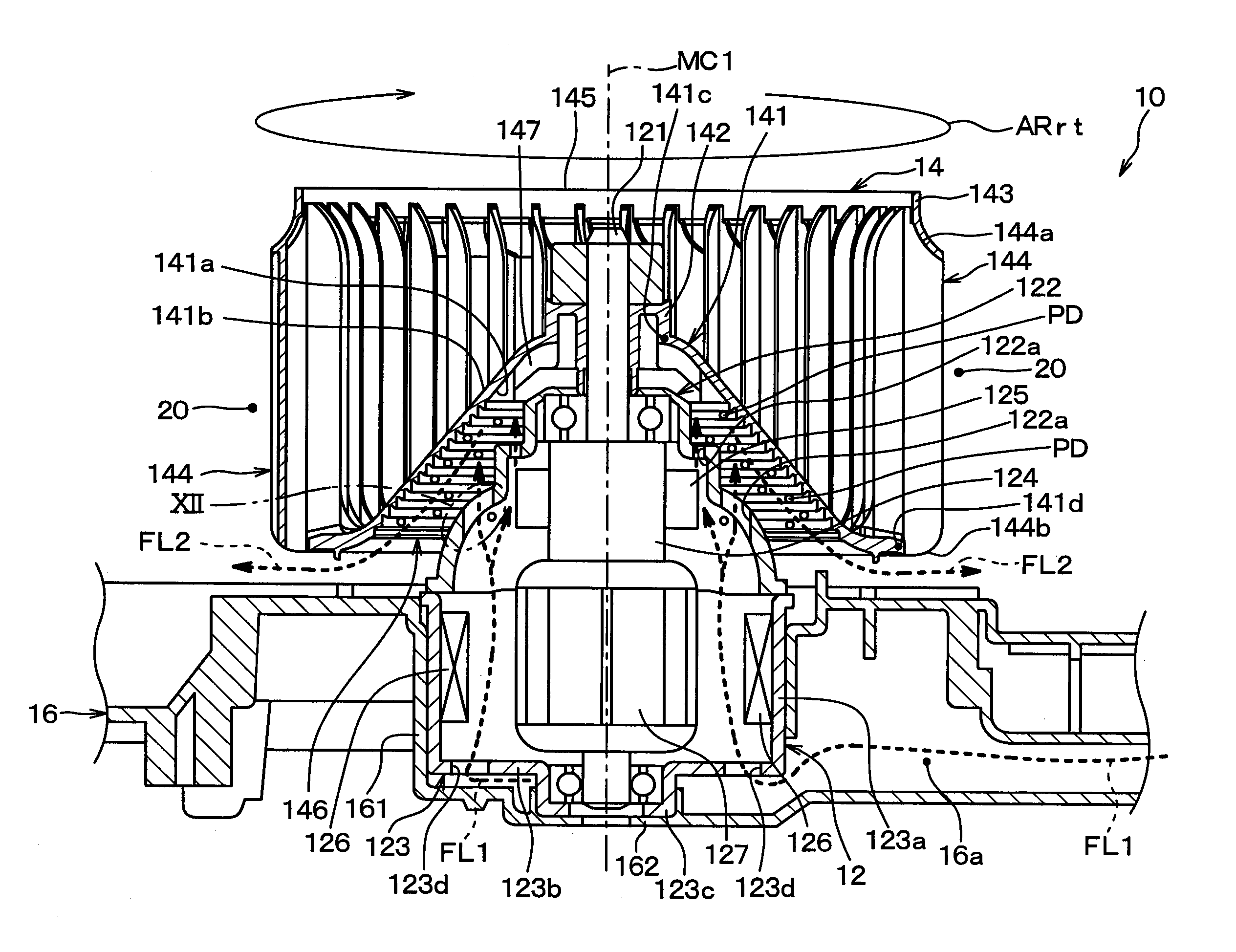
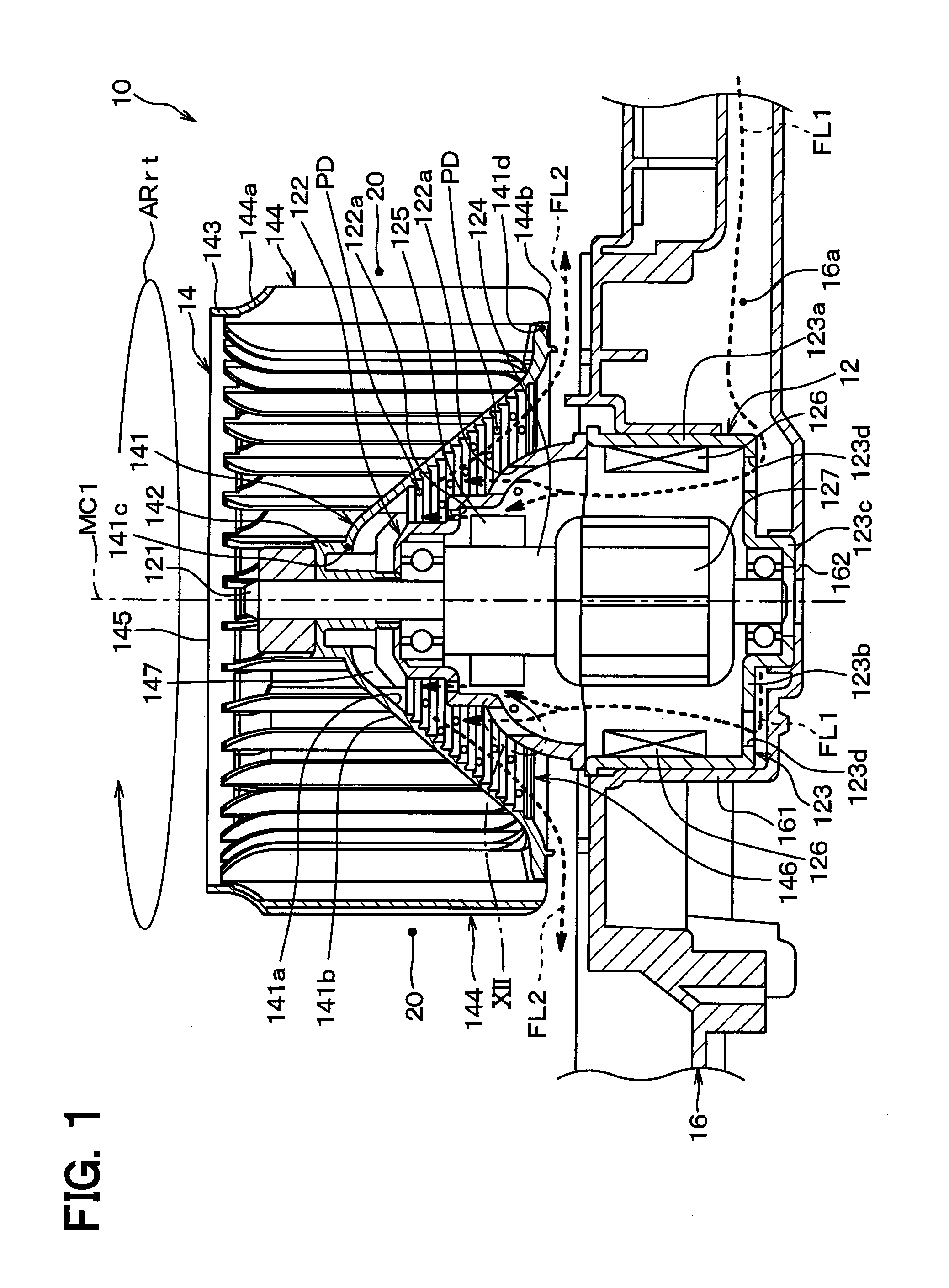
[0027]A first embodiment is described. FIG. 1 is a sectional view illustrating an electric motor 12 and an impeller 14 of a centrifugal multiblade blower 10 (henceforth referred to the blower 10) of the first embodiment. The blower 10 shown in FIG. 1 is adopted in an air-conditioner for a vehicle, which blows off conditioned air into a passenger compartment of the vehicle, and is operated to send air for conditioning. The blower 10 is, specifically, a sirocco fan.

[0028]The blower 10 is received in an air-conditioning case (not shown) made of resin material, and an air passage through which the air-conditioning air flows is formed downstream of the blower 10 in a flow of air by the air-conditioning case. An evaporator (not shown) which cools the air-conditioning air is disposed downstream of the blower 10 in the flow of air in the air passage. Air leak is prevented by a seal material made of rubber around the evaporator. In FIG. 1, one-point chain line MC1 represents a motor axial ce...

second embodiment

[0068]A second embodiment is described. In this embodiment, a point different from the first embodiment is mainly explained, and explanation of a portion the same or equal to the first embodiment is omitted or simplified. This is the same in the third embodiment and the subsequent embodiments mentioned below.

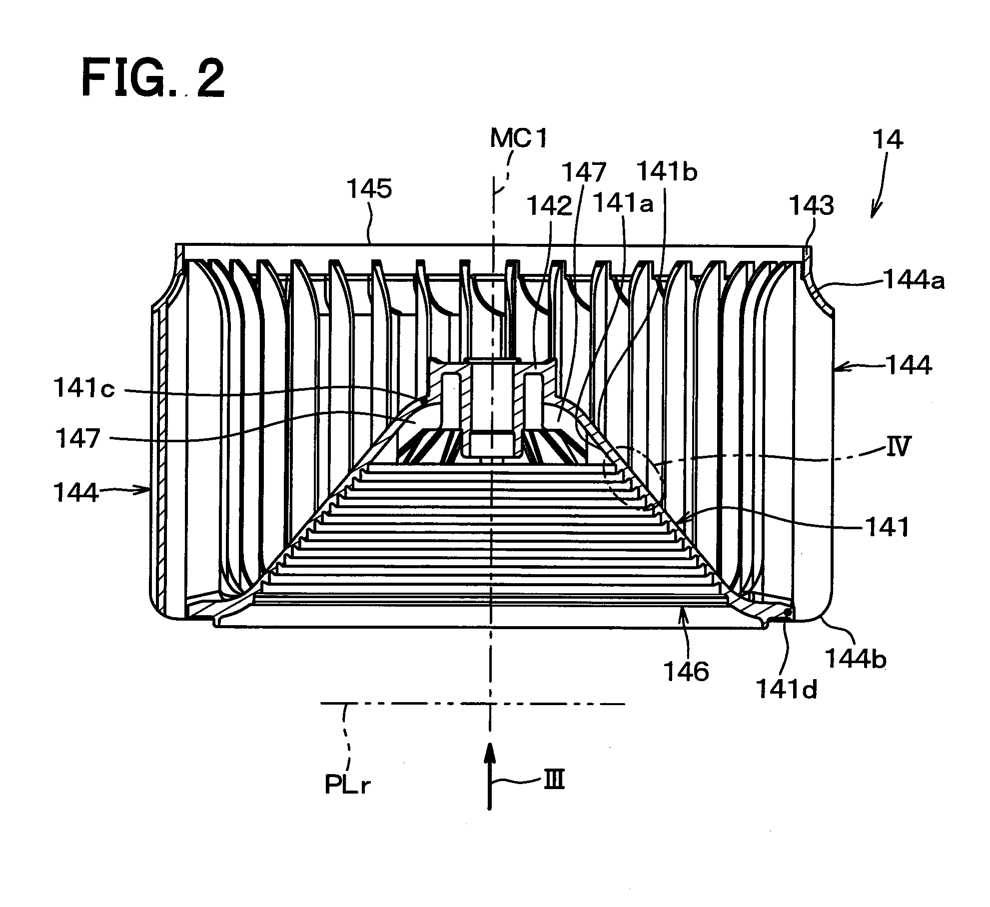
[0069]FIG. 5 is a view in which the impeller 14 of the blower 10 of this embodiment is seen in the arrow direction III of FIG. 2, and corresponds to FIG. 3 of the first embodiment. In this embodiment, the number of the radial ribs 147 of the impeller 14 adjacent to the electric motor 12 is reduced, compared with the first embodiment, which is easily understood by comparing FIG. 5 with FIG. 3. This is the point different from the first embodiment, and the other portion is the same as the first embodiment. Concretely, the number of the radial ribs 147 in this embodiment is eight as shown in FIG. 5.

[0070]Therefore, according to this embodiment, compared with the first embodiment, t...

third embodiment

[0071]A third embodiment is described. A point different from the first embodiment is mainly explained.

[0072]FIG. 6 is a view in which the impeller 14 of the blower 10 of this embodiment is seen in the arrow direction III of FIG. 2, and corresponds to FIG. 3 of the first embodiment. As shown in FIG. 6, in this embodiment, the uneven part 146 on the main plate 141 of the impeller 14 has plural connection ribs 148 which connect the adjacent protrusion parts 146a in the motor radial direction. This is the point different from the first embodiment, and the other portion is the same as the first embodiment.

[0073]As shown in FIG. 6, eight of the connection ribs 148 extend radially in the motor radial direction. In detail, as shown in FIG. 7 and FIG. 8, each of the connection ribs 148 is formed to project toward the electric motor 12 in the main plate 141, and is formed so that the amount of projection, i.e., rib height, may not exceed the top part 146d of the protrusion part 146a. FIG. 7 ...


PUM


Abstract

A centrifugal multiblade blower includes: an electric motor; and an impeller blowing off air outward in a radial direction by being rotated by the electric motor. A main plate of the impeller has an uneven part on one surface adjacent to the electric motor in a thickness direction of the main plate. The one surface is in contact with air passing through inside of the electric motor. A surface shape of the uneven part is formed in manner that, among a whole surface of the uneven part, a total surface area of a surface facing inward in a radial direction of the motor is larger than an imaginary smooth surface on which the surface shape of the uneven part is defined to be a smooth surface without the uneven part.

Description

CROSS REFERENCE TO RELATED APPLICATION[0001]This application is based on Japanese Patent Application No. 2014-51818 filed on Mar. 14, 2014, the disclosure of which is incorporated herein by reference.TECHNICAL FIELD[0002]The present disclosure relates to a structure of centrifugal multiblade blower rotated by an electric motor, in particular, to a structure of an impeller of the centrifugal multiblade blower.BACKGROUND ART[0003]Patent Literature 1 describes a centrifugal multiblade blower such as sirocco fan or turbo fan. The blower is equipped with an electric motor and an impeller rotated by the electric motor to blow off air outward in a radial direction.[0004]The impeller has plural blades arranged around a rotation shaft of the electric motor, and a main plate holding the blades and transmitting the rotation power generated by the electric motor to the blades. The main plate has a main part in which plural penetration holes are arranged in the circumferential direction, and a b...

Claims


Application Information

Patent Timeline
IPC IPC(8): F04D25/06H02K7/00F04D29/28F04D29/42F04D25/08
CPCF04D25/06F04D29/4226H02K7/003F04D29/281F04D25/082F04D29/289F05D2250/181F05D2250/294H02K7/14H02K9/06H02K9/26H02K9/28
Inventor KAMIYA, TOSHIFUMISHIRAISHI, HIROAKI
Owner DENSO CORP
Why Eureka
Try Eureka