

Imaging unit, lens barrel, and portable terminal
- Summary
- Abstract
- Description
- Claims
- Application Information
AI Technical Summary
Benefits of technology
Problems solved by technology
Method used
Image

Examples
first embodiment
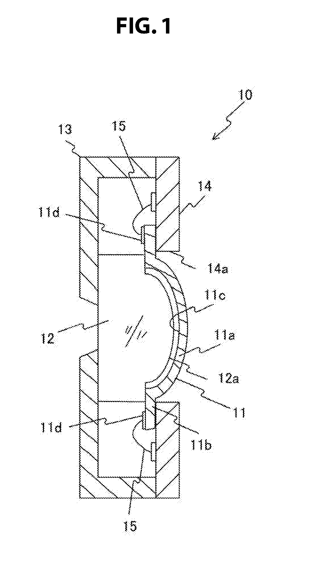
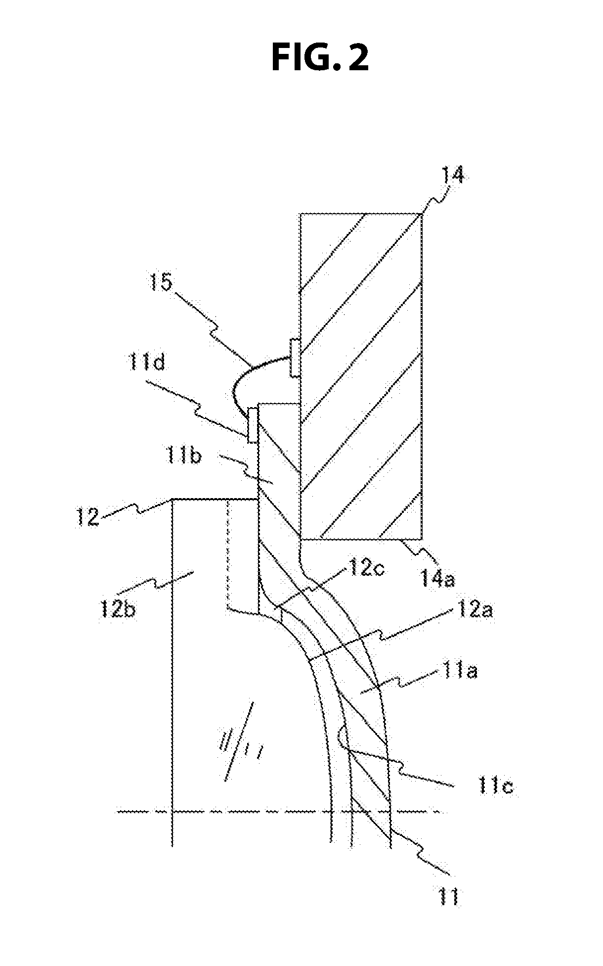
[0047]FIG. 1 is a cross-sectional view of an imaging unit 10 according to a first embodiment. FIG. 2 is an enlarged cross-sectional view of a portion of the imaging unit 10.
[0048]As illustrated in FIG. 1, the imaging unit 10 includes a CMOS imaging element 11, an imaging lens 12, a housing 13, and a substrate 14 holding the imaging element 11, which are integrally formed. The CMOS imaging element 11 is a solid-state imaging element having an imaging surface 11c as a photoelectric conversion part. The imaging lens 12 is a lens for capturing a subject image on an imaging surface 11c on the imaging element 11. The housing 13 includes a light-shielding member having an aperture for receiving light incident from the object side.
[0049]The intermediate product of the imaging element 11 has a flat-plate shape and is curved into a hemispherical shape with a predetermined radius of curvature by being compressed from the outer peripheral side, and the imaging element 11 includes a central curv...
second embodiment
[0060]FIG. 5 is a cross-sectional view of an imaging unit 10A according to a second embodiment, with the housing being omitted. In the present embodiment, a substrate 14A has a cylindrical concave part 14b, with a portion of the imaging element 11 being accommodated in the concave part 14b. The rest of the configuration is similar to the aforementioned embodiment.
third embodiment
[0061]FIG. 6 is a cross-sectional view of an imaging unit 10B according to a third embodiment, with the housing being omitted. In the present embodiment, the entire back side (the side opposite to the imaging lens 12) of the block-shaped imaging element 11 B is adhesively fixed to a parallel flat-plate substrate 14B, and the flange part 12b of the imaging lens 12 abuts on the object side face of the flat-plate part 11b of the imaging element 11A to be adhesively fixed thereto. The rest of the configuration is similar to the aforementioned embodiment.
PUM
 Abstract
Description
Claims
Application Information