Discharge lamp lighting circuit

Inactive Publication Date: 2002-09-12
KOITO MFG CO LTD
View PDF0 Cites 5 Cited by
  • Summary
  • Abstract
  • Description
  • Claims
  • Application Information

AI Technical Summary

Benefits of technology

0022] According to the invention, therefore, the output voltage on the non-load side is limited to the output voltage having a reverse polarity

Problems solved by technology

Moreover, in the case in which the number of the discharge lamps is two, there is a disadvantage in that the number of components and a cost cannot be reduced if respective lighting circuits corresponding to the discharge lamps are provided to light up the discharge lamp.
With the structure described above, however, the following drawbacks might be caused, for example.
(1) The influence of an AC component (based on a pulsating flow) with a low lighting frequency hinders constant power control;
(3) An increase in a loss in a current auxiliary circuit.
Therefore, a current is increased immediately after the polarity inversion and the pulsating flow causes a great fluctuation in an output voltage, resulting in bad effects (1) to (3).
However, when the capacity of the smoothing capacitor

Method used


Image

  • Discharge lamp lighting circuit
  • Discharge lamp lighting circuit
  • Discharge lamp lighting circuit

Examples


Embodiment Construction

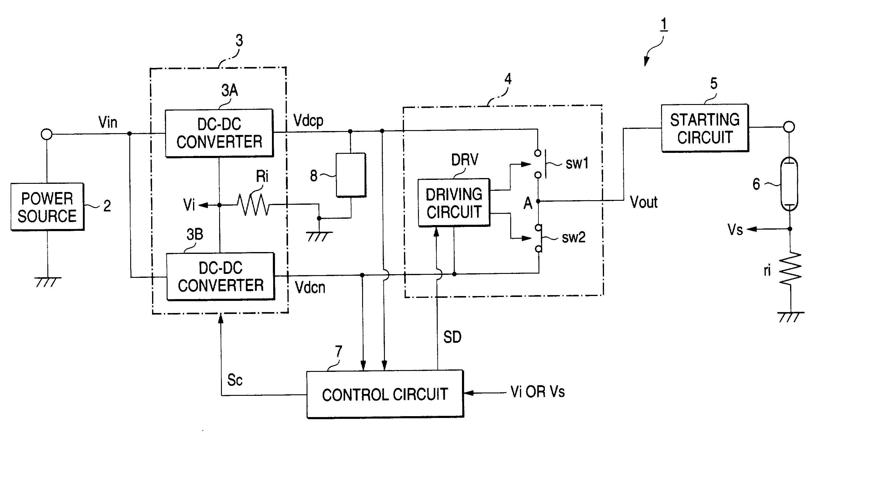
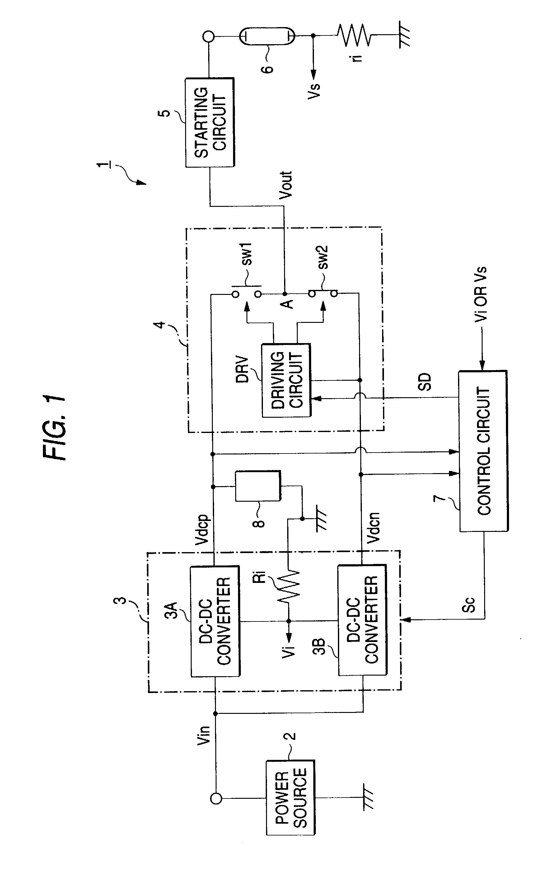
[0035] Referring to the case in which one discharge lamp is provided, first of all, the structure of a lighting circuit according to the invention will be described with reference to FIG. 1.

[0036] A discharge lamp lighting circuit 1 comprises a DC power source 2, a DC-DC converting circuit 3, a DC-AC converting circuit 4 and a starting circuit 5.

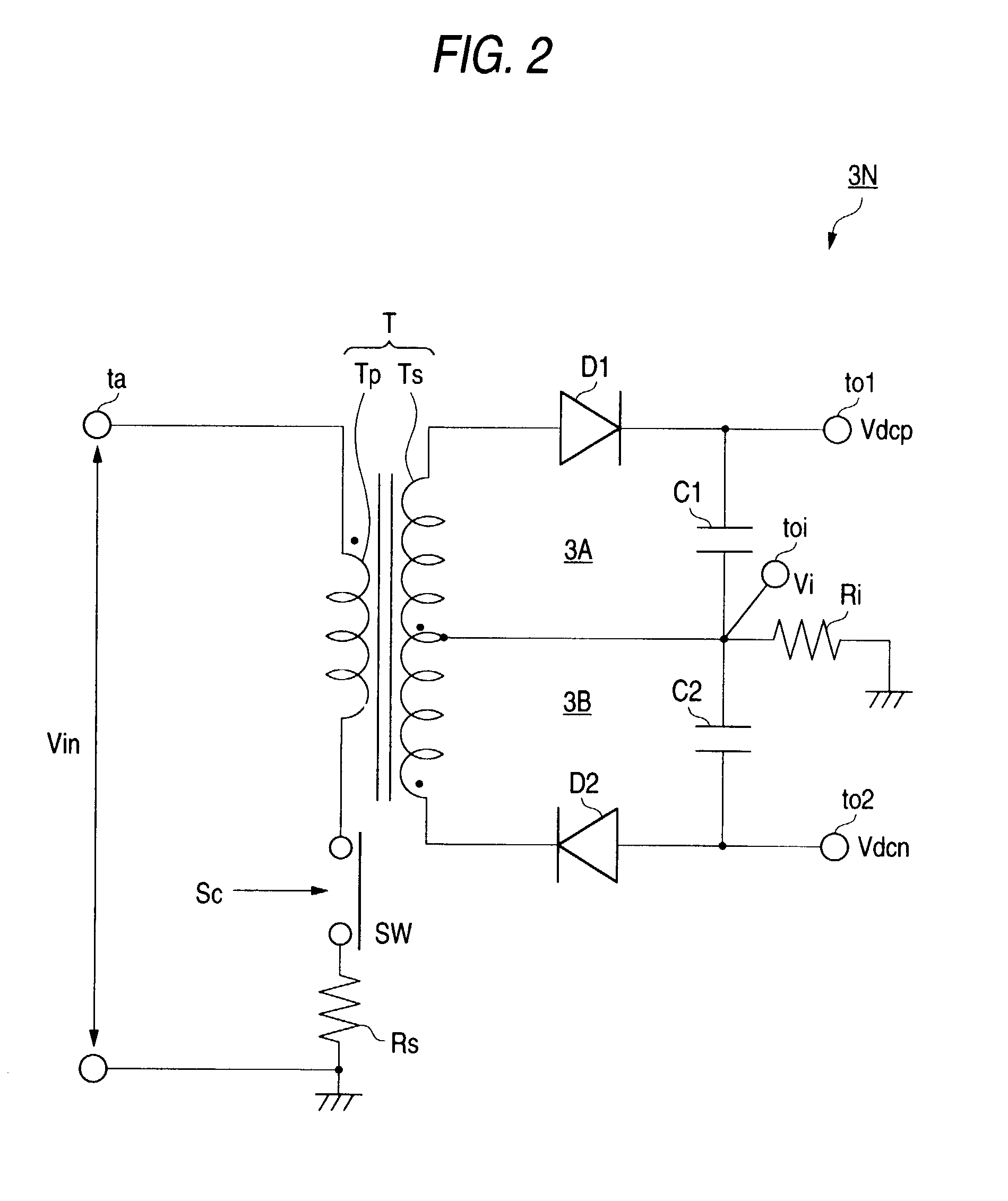
[0037] The DC-DC converting circuit 3 serves to obtain outputs having positive and negative polarities upon receipt of a DC input voltage (indicated as "Vin") which is applied from the power source 2, and has a transformer and a switching element in the circuit. In addition, the switching element is controlled in response to a signal sent from a control circuit 7 and an output voltage thereof is controlled. A DC-DC converter (a flyback type) having the structure of a switching regulator is used for the DC-DC converting circuit 3. As described above, there are a configuration of a non-isolation type in which circuits for obtaining both output...


PUM


Abstract

When alternately applying an output voltage of a DC-DC converting circuit 3 to one discharge lamp, an output voltage on a non-load side in outputs having positive and negative polarities which is not applied to the discharge lamp during the light-up of the discharge lamp is restricted to be equal to an output voltage on a side which is applied to the discharge lamp. Moreover, when supplying a power to two discharge lamps while alternately switching a polarity of an output voltage through the DC-DC converting circuit 3, an output voltage on a non-load side in the outputs having positive and negative polarities which is not applied to the discharge lamp is restricted to be equal to the output voltage on the side which is applied to the discharge lamp if one of the discharge lamps is lighted up or an instruction for light-up is given and the other discharge lamp is lighted out or an instruction for light-out is given.

Description

BACKGROUND OF THE INVENTION[0001] The present invention relates to a technique for reducing a power loss and heat generation in a discharge lamp lighting circuit and for guaranteeing stable lighting control.[0002] There has been known a lighting circuit for a discharge lamp (a metal halide lamp) comprising a DC-DC converting circuit, a DC-AC converting circuit and a starting circuit (a so-called starter circuit). Assuming that the number of discharge lamps is one, for example, there is a structure comprising a DC-DC converter, a half bridge type circuit (a circuit constituted to make a set of two semiconductor switching elements and to alternately carry out ON / OFF control) and a control circuit thereof. The output of the converter is controlled by the control of the switching element in the DC-DC converter and an AC output generated by the alternating operation of the switching element constituting the half bridge type circuit is supplied to the discharge lamp. The DC-DC converter i...

Claims


Application Information

Patent Timeline
IPC IPC(8): H05B41/282H05B41/285H05B41/292
CPCH05B41/285H05B41/292Y02B20/183Y02B20/00
Inventor ITO, MASAYASUTAKEDA, HITOSHI
Owner KOITO MFG CO LTD
Why Eureka
Try Eureka