Imaging lens
a technology of imaging and lens, applied in the field of imaging lenses, can solve the problems of inability to obtain excellent optical performance and difficulty in correcting aberration at the peripheral area, and achieve the effects of low f-number, correcting aberration properly, and high resolution
- Summary
- Abstract
- Description
- Claims
- Application Information
AI Technical Summary
Benefits of technology
Problems solved by technology
Method used
Image

Examples
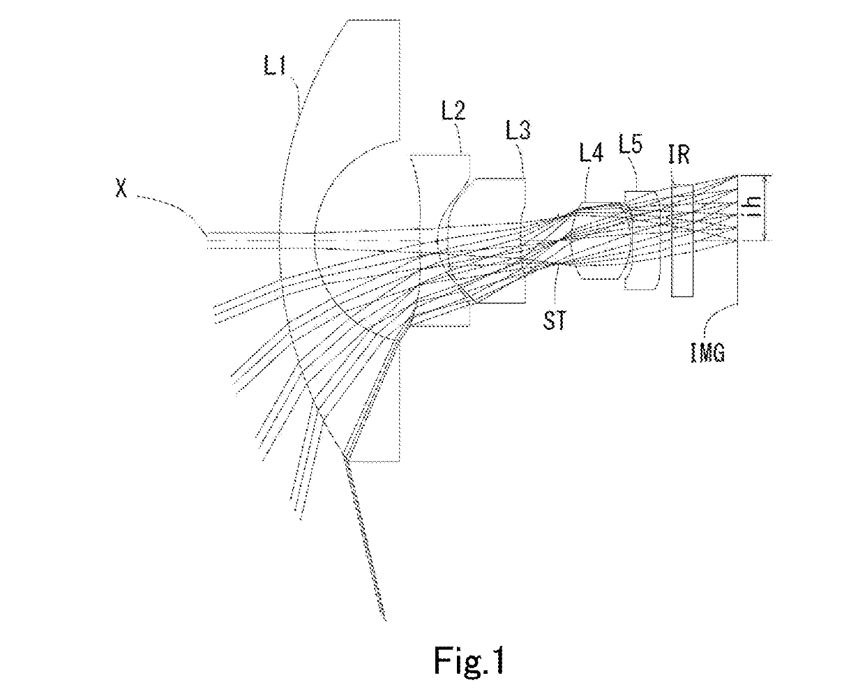
example 1
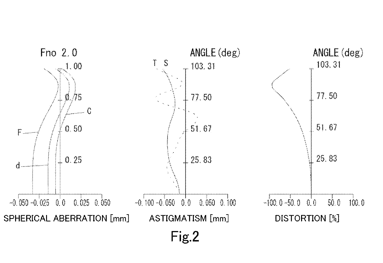
[0158]The basic lens data is shown below in Table 1.
TABLE 1Example 1Unit mmf = 0.93Fno = 2.0ω(°) = 103.3ih = 1.85TTL = 12.76Surface DataSurfaceCurvatureSurfaceRefractiveAbbeNumber iRadius rDistance dIndex NdNumber νd(Object)InfinityInfinity111.06361.00001.74444.72 (νd1)22.88862.9813 3*28.00000.50001.54455.86 (νd2) 4*1.80000.2870 5*7.42392.07131.66120.37 (νd3) 6*30.51011.06687 (Stop)Infinity0.359782.07791.69101.55371.68 (νd4)9−1.79780.050010*−1657.81000.77301.66120.37 (νd5)11*27.38660.330212 Infinity0.61001.51764.1713 Infinity1.2488Image PlaneInfinityConstituent Lens DataLensStart SurfaceFocal LengthComposite Focal LengthBack Focus11−5.544f123−1.939b f1.98123−3.5583514.337482.063510−40.767Aspheric Surface DataThird SurfaceFourth SurfaceFifth SurfaceSixth SurfaceTenth SurfaceEleventh Surfacek 0.000000E+00−1.040000E+01 0.000000E+000.000000E+000.000000E+000.000000E+00A4−1.548087E−032.336991E−011.119540E−011.003553E−01−4.806784E−02 2.241104E−03A6−1.771412E−02−9.614101E−02 5.558553E−03−1....
example 2
[0161]The basic lens data is shown below in Table 2.
TABLE 2Example2Unit mmf = 0.93Fno = 2.0ω(°) = 103.3ih = 1.85TTL = 12.76Surface DataSurfaceCurvatureSurfaceRefractiveAbbeNumber iRadius rDistance dIndex NdNumber νd(Object)InfinityInfinity111.06361.00001.74444.72 (νd1)22.88862.9940 3*28.00000.50001.53556.16 (νd2) 4*1.80000.2879 5*7.64532.04591.66120.37 (νd3) 6*33.40171.07387 (Stop)Infinity0.347482.09381.69951.55371.68 (νd4)9−1.79250.050010*−232.66560.78141.66120.37 (νd5)11*31.04190.330812 Infinity0.61001.51764.1713 Infinity1.2473Image PlaneInfinityConstituent Lens DataLensStart SurfaceFocal LengthComposite Focal LengthBack Focus11−5.544f123−1.966b f1.98023−3.6223514.546482.067510−41.401Aspheric Surface DataThird SurfaceFourth SurfaceFifth SurfaceSixth SurfaceTenth SurfaceEleventh Surfacek 0.000000E+00−1.080000E+01 0.000000E+000.000000E+000.000000E+000.000000E+00A4−3.904487E−032.398638E−011.152417E−011.023612E−01−4.978045E−02 −2.296058E−03 A6−1.681899E−02−9.918802E−02 3.814480E−03−2....
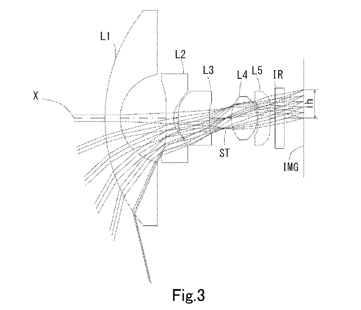
example 3
[0164]The basic lens data is shown below in Table 3.
TABLE 3Example3Unit mmf = 0.93Fno = 2.0ω(°) = 103.6ih = 1.85TTL = 12.75Surface DataSurfaceCurvatureSurfaceRefractiveAbbeNumber iRadius rDistance dindex NdNumber νd(Object)InfinityInfinity111.27781.00001.74444.72 (νd1)23.02952.6327 3*28.00000.50001.53556.16 (νd2) 4*1.80000.6796 5*5.30732.33331.66120.37 (νd3) 6*5.70860.81867 ( Stop )infinity0.000082.04512.01591.55075.50 (νd4)9−1.73670.050010*17.13920.74991.66120.37 (νd5)11*80.90750.319712 Infinity0.61001.51764.1713 Infinity1.2482Image PlaneInfinityConstituent Lens DataLensStart SurfaceFocal LengthComposite Focal LengthBack Focus11−5.871f123−1.623b f1.97023−3.6223534.485482.10551032.758Aspheric Surface DataThird SurfaceFourth SurfaceFifth SurfaceSixth SurfaceTenth SurfaceEleventh Surfacek−9.738778E−05−5.150000E−01−8.692110E−090.000000E+00 0.000000E+00 0.000000E+00A4 2.890614E−01 5.757366E−01 1.767472E−017.075482E−02−9.200815E−02−5.653677E−03A6−2.281365E−01−1.106851E−01−1.185494E−01−9....
PUM
 Abstract
Description
Claims
Application Information
 - R&D
- Intellectual Property
- Life Sciences
- Materials
- Tech Scout
- Unparalleled Data Quality
- Higher Quality Content
- 60% Fewer Hallucinations
Browse by: Latest US Patents, China's latest patents, Technical Efficacy Thesaurus, Application Domain, Technology Topic, Popular Technical Reports.
© 2025 PatSnap. All rights reserved.Legal|Privacy policy|Modern Slavery Act Transparency Statement|Sitemap|About US| Contact US: help@patsnap.com