Techniques for implementing fault domain sets

Active Publication Date: 2019-08-01
SALESFORCE COM INC
View PDF7 Cites 12 Cited by
  • Summary
  • Abstract
  • Description
  • Claims
  • Application Information

AI Technical Summary

Problems solved by technology

Having a virtual machine for each application, however, usually results in many duplicate instances of the same operating system and many redundant boot volumes.
Thus, running many applications becomes expensive.
Programs such as Docker™ may not always be efficient at deploying containerized applications across multiple computer systems, as each computer sy

Method used


Image

  • Techniques for implementing fault domain sets
  • Techniques for implementing fault domain sets
  • Techniques for implementing fault domain sets

Examples


Embodiment Construction

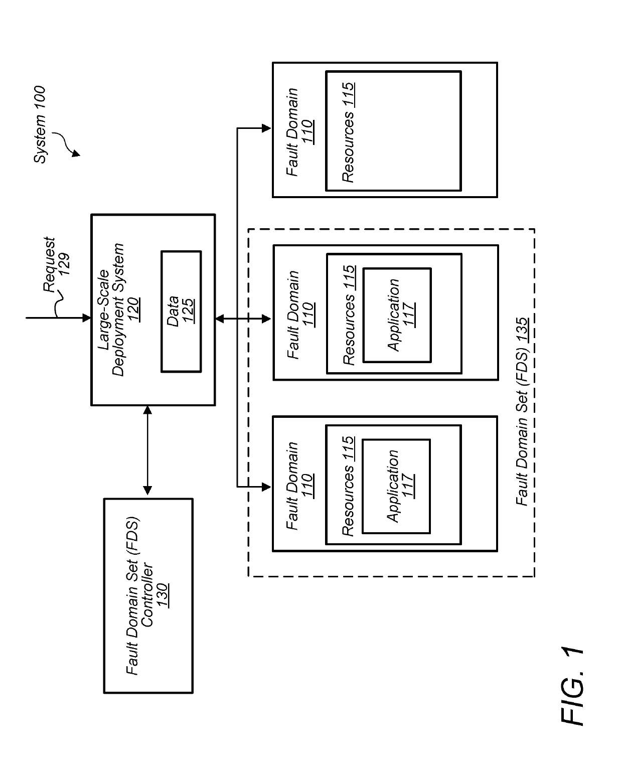
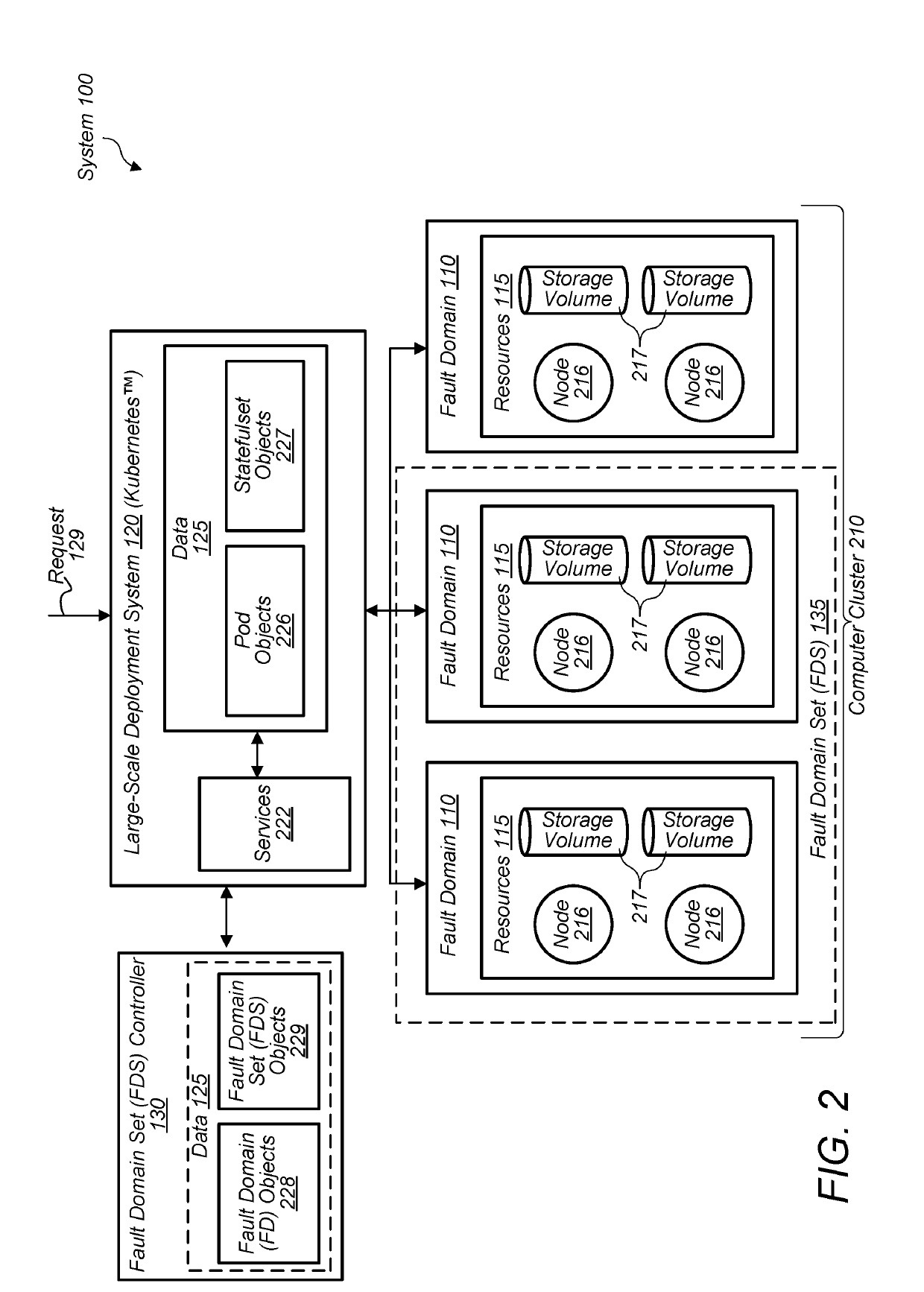
[0017]In a data processing center (e.g., a server warehouse), there may be multiple server systems that are grouped together as a result of the underlying infrastructure. For example, a data processing center may include multiple server racks, which each include a group of server systems. A server rack may be considered a fault domain. As used herein, the term “fault domain” refers to a set of hardware components that share at least one common point of failure. For a server rack, the point of failure may be a power supply that supplies power to all server systems in that rack. If that power supply fails, then all server systems in that rack will crash. Accordingly, in order to ensure that an application / service is almost always available and to avoid the issues of a single fault domain, a provider of the application may want to run that application on hardware within multiple fault domains. A grouping of one or more fault domains is referred to herein as a fault domain set. As such,...


PUM


Abstract

Techniques are disclosed relating to provisioning fault domain sets (FDS). In some embodiments, a computer server system implements an FDS for disseminating a storage service across a plurality of fault domains. To implement the FDS, in some embodiments, the computer server system access FDS data specifying a desired state of the FDS in which the storage service is disseminated across at least a particular number of fault domains. The computer server system may determine available resources of the plurality of fault domains and determine a current state of the FDS based on fault domains that have already been provisioned to the FDS. Based on at least the desired state of the FDS, the current state of the FDS, and the available resources, the computer server system provisions one or more additional fault domains to the FDS to reconcile the FDS's current state with the FDS's desired state.

Description

BACKGROUNDTechnical Field[0001]This disclosure relates generally to storage systems and, more specifically, the dissemination of services across fault domains.Description of the Related Art[0002]Large-scale computer systems have typically run applications inside their own virtual machines. Having a virtual machine for each application, however, usually results in many duplicate instances of the same operating system and many redundant boot volumes. Thus, running many applications becomes expensive. Accordingly, there has been a movement towards containerization. Particularly, an application and its dependencies can be packaged into a portable, self-sufficient unit called a container. Once a container has been generated, it may be provided to a computer system running a program such as Docker™ that handles instantiating the containerized application on that computer system. Multiple containers may be deployed on the same computer system without having to create a virtual machine for ...

Claims


Application Information

Patent Timeline
IPC IPC(8): G06F3/06G06F11/20
CPCG06F3/0632G06F3/0604G06F3/0619G06F3/0631G06F3/0644G06F3/067G06F11/2094G06F2201/805G06F2201/82G06F9/455G06F8/60G06F11/0727
Inventor ZWIEGINCEW, ARTHURGRASS, MICHAELCHAKERES, IANHEGDE, DHIRAJ
Owner SALESFORCE COM INC
Why Eureka
Try Eureka