Eureka AIR delivers breakthrough ideas for toughest innovation challenges, trusted by R&D personnel around the world.

Method implemented in an electronic entity and associated electronic entity

Active Publication Date: 2019-08-01
IDEMIA FRANCE
View PDF23 Cites 0 Cited by
  • Summary
  • Abstract
  • Description
  • Claims
  • Application Information

AI Technical Summary

Benefits of technology

The present invention proposes a method and electronic entity for triggering an indication when a user selects an application among a plurality of applications. This indication can remind the user which application is currently selected. The method involves detecting an electrical signal, such as a voltage or a magnetic field, and transmitting a command to deliver the indication. The electronic entity can be a microcontroller or a microcircuit card, and the indication can be displayed on a screen or using a light-emitting diode. The invention provides a convenient way for users to quickly and easily select their desired applications.

Problems solved by technology

It is not however applicable when the electronic entity makes it possible for a previous selection of the application to use, without intervention of the reader.

Method used


Image

  • Method implemented in an electronic entity and associated electronic entity
  • Method implemented in an electronic entity and associated electronic entity

Examples


Embodiment Construction

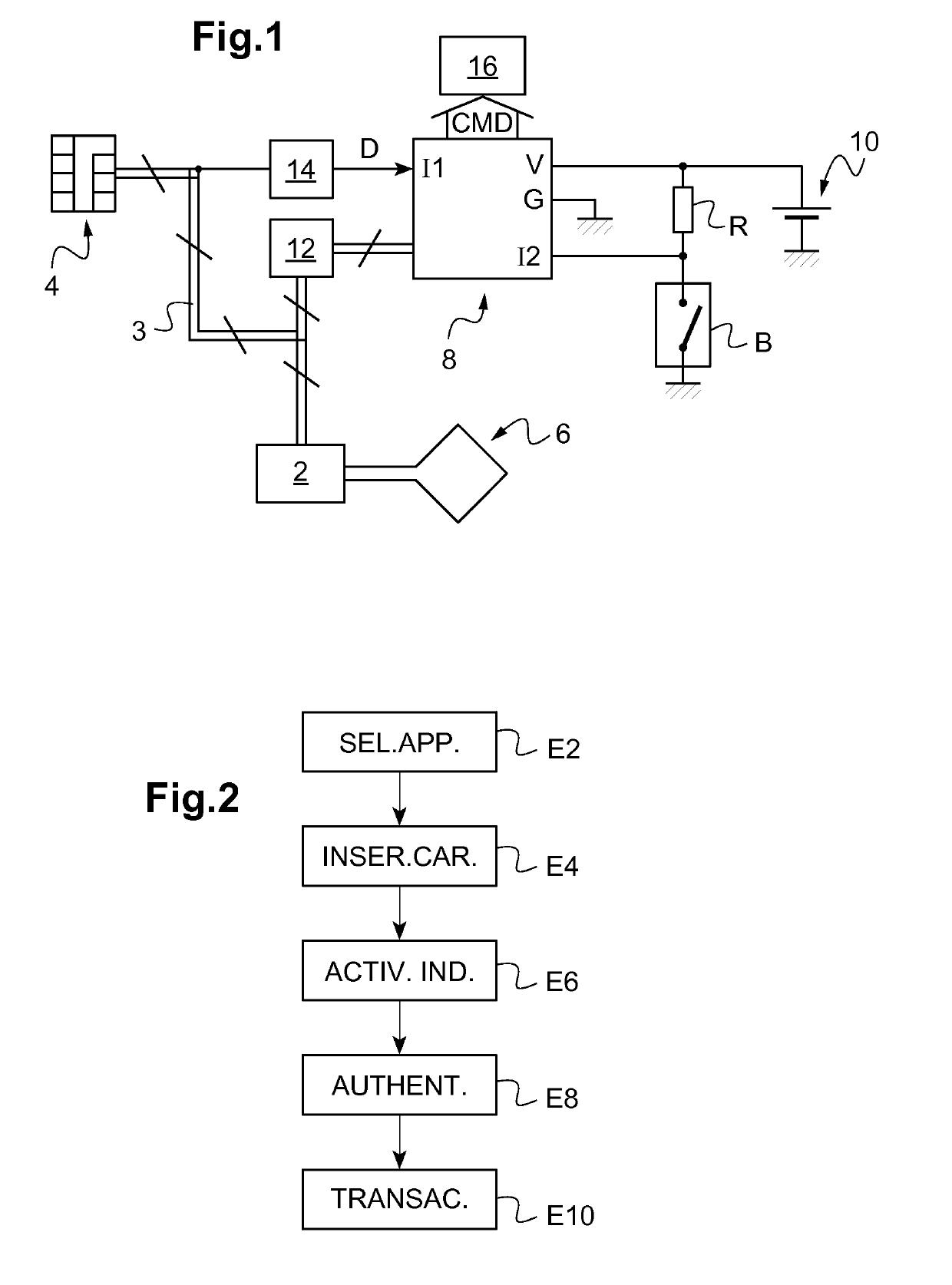
[0037]FIG. 1 schematically represents the main elements of a first example of an electronic entity, here a microcircuit card, which conforms with the invention.

[0038]The microcircuit card of FIG. 1 comprises a processor 2 connected to a contact interface 4 by means of a bus 3, here a bus which conforms with the standard ISO / IEC 7816.

[0039]The processor 2 is, for example, a secure element, such as an integrated circuit making it possible to execute (here in the scope of the EMV standard) an application selected among several applications (or applets) stored within the processor 2.

[0040]The contact interface 4 here comprises (in conformity with the abovementioned standard ISO / IEC 7816) eight contacts referenced C1 to C8, with a supply contact C1, a reinitialization contact C2, a clock contact C3, a ground contact C5, a programming contact C6, an input / output contact C7 and two unused contacts C4, C8.

[0041]These contacts are flush with the upper surface of the microcircuit card. When t...


PUM


Abstract

A method implemented in an electronic entity capable of implementing a plurality of applications includes the following steps: detecting an electrical signal (D; D′); reading, in a memory of the electronic entity, information relating, among the plurality of applications, to a previously selected application; and transmitting a command (CMD) to deliver an indication associated with the application to which the read information relates. An associated electronic entity is also described.

Description

BACKGROUND OF THE INVENTIONField of the Invention[0001]The present invention relates to the electronic entities (such as microcircuit cards) designed to implement a plurality of applications.[0002]It relates more specifically to a method implemented in an electronic entity and an associated electronic entity.[0003]The invention is particularly advantageously applied in the case where the electronic entity makes it possible for the user to select, by interaction with the single electronic entity, the application to use.Description of the Related Art[0004]In the electronic entities designed to implement a plurality of applications, it has already been proposed as described for example in document EP 2 395 460, to control an indicator of the electronic entity in a configuration representative of the application selected at a reader communicating with the electronic entity.[0005]This solution makes it possible to simply inform the user regarding the application actually selected by the ...

Claims


Application Information

Patent Timeline
IPC IPC(8): G06K19/067G06K19/06G07F7/08
CPCG06K19/0677G06K19/06196G07F7/0873G06K19/0702G06K19/0719G06K19/0723G06K19/07703G06K19/07705G06K19/07707
Inventor GUILLAUD, PHILIPPEDUONG, BASTIEN
Owner IDEMIA FRANCE
Why Eureka
Eureka Blog
Learn More