Methods and apparatus for the mounting of antenna apparatus

Active Publication Date: 2019-08-01
PULSE FINLAND
View PDF0 Cites 1 Cited by
  • Summary
  • Abstract
  • Description
  • Claims
  • Application Information

AI Technical Summary

Benefits of technology

[0010]The aforementioned needs are satisfied herein by providing antenna apparatus, systems and methods that provide for, inter alia, simple and more convenient antenna installation in, for example, in-building environments, while simultaneously providing for desirable operati

Problems solved by technology

As a result, wireless networks have prioritized capacity demands which have often times come at the expense of wireless coverage.
However, antennas such as those desc

Method used


Image

  • Methods and apparatus for the mounting of antenna  apparatus
  • Methods and apparatus for the mounting of antenna  apparatus
  • Methods and apparatus for the mounting of antenna  apparatus

Examples


Example

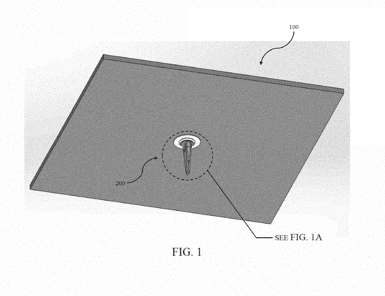
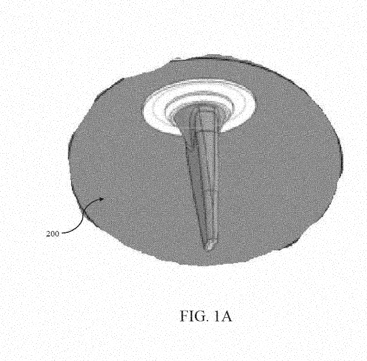
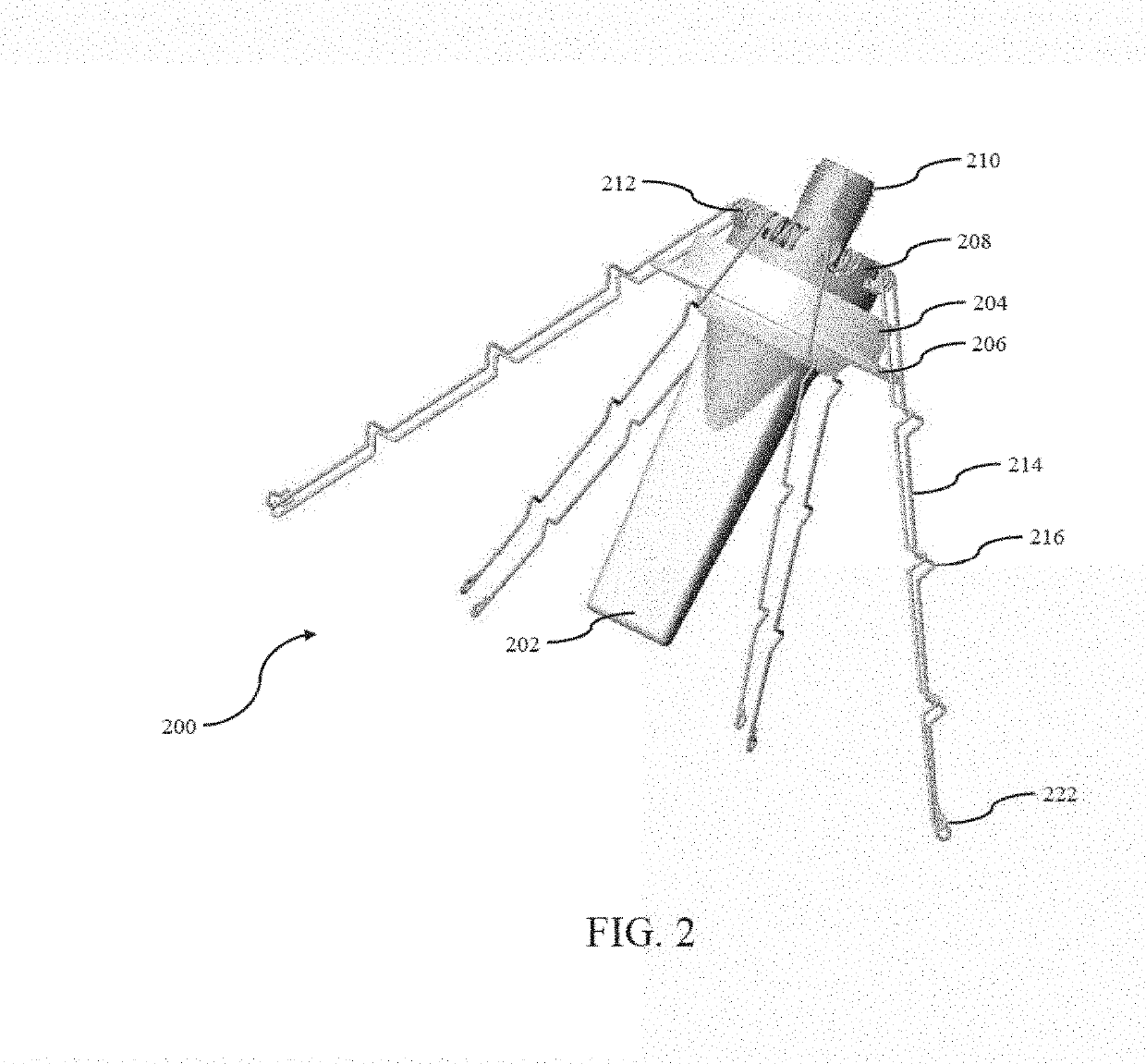
[0040]Reference is now made to the drawings wherein like numerals refer to like parts throughout.

[0041]As used herein, the term “antenna” refers without limitation to any system that incorporates a single element, multiple elements, or one or more arrays of elements that receive / transmit and / or propagate one or more frequency bands of electromagnetic radiation. The radiation may be of numerous types, e.g., microwave, millimeter wave, radio frequency, digital modulated, analog, analog / digital encoded, digitally encoded millimeter wave energy, or the like. The energy may be transmitted from location to another location, using, one or more repeater links, and one or more locations may be mobile, stationary, or fixed to a location on earth such as a base station.

[0042]As used herein, the term “feed” refers without limitation to any energy conductor and coupling element(s) that can transfer energy, transform impedance, enhance performance characteristics, and conform impedance properties...


PUM


Abstract

In-building antenna apparatus and methods for manufacturing and installing the same. In one embodiment, the antenna apparatus includes a radome cover, a lower flange, an antenna housing, a spring-loaded mount apparatus, a signaling interface, and a plurality of spring arms. Each of the spring arms may include at least one tie-down location. Accordingly, when a removable tie is placed around a plurality of tie-down locations, the antenna apparatus resides in an installation configuration; however, when the removable tie is removed from around the plurality of tie-down locations, the antenna apparatus transitions towards a default configuration. The spring arms may also act as a ground plane for the antenna. Spring-loaded mount apparatus as well as methods of manufacturing and installing the aforementioned antenna apparatus are also disclosed.

Description

PRIORITY[0001]This application claims the benefit of priority to co-owned and co-pending U.S. Provisional Patent Application Ser. No. 62 / 622,660 of the same title, filed Jan. 26, 2018, the contents of which being incorporated by reference herein in its entirety.RELATED APPLICATIONS[0002]This application is related to co-owned and co-pending U.S. patent application Ser. No. 14 / 472,170 entitled “Low Passive Intermodulation Distributed Antenna System for Multiple-Input Multiple-Output Systems and Methods of Use”, filed Aug. 28, 2014, and co-owned and co-pending U.S. patent application Ser. No. 14 / 964,374 entitled “Broadband Omni-Directional Dual-Polarized Antenna Apparatus and Method of Manufacturing and Use”, filed Dec. 9, 2015, each of the foregoing being incorporated herein by reference in its entirety.COPYRIGHT[0003]A portion of the disclosure of this patent document contains material that is subject to copyright protection. The copyright owner has no objection to the facsimile rep...

Claims


Application Information

Patent Timeline
IPC IPC(8): H01Q1/12H01Q1/42H01Q1/00H01Q9/32H01Q1/48
CPCH01Q1/1214H01Q1/42H01Q1/007H01Q9/32H01Q1/48H01Q1/22H01Q1/50H01Q9/30H01Q1/2291H01Q9/38
Inventor GE, ZACKYUAN, JAY
Owner PULSE FINLAND
Why Eureka
Try Eureka