a ring compressor

A compressor and annular technology, which is applied in the field of annular compressors, can solve the problems of not considering the effect of gas force on the stationary slider, not giving an operable driving method, and the difficulty of keeping the stationary slider stationary, etc., so as to improve the electromechanical conversion Efficiency, simple structure, and improved electromagnetic properties

Active Publication Date: 2016-06-22
HUAZHONG UNIV OF SCI & TECH
View PDF8 Cites 0 Cited by
  • Summary
  • Abstract
  • Description
  • Claims
  • Application Information

AI Technical Summary

Problems solved by technology

However, it is difficult to ensure the reliability of positioning by exchanging the motion state of the slider through elastic collision
Frequent collisions cause noise, material fatigue, and consume kinetic energy reducing energy efficiency
This structure does not consider the effect of gas force on the stationary slider. In fact, the pressure difference between the high pressure side and the low pressure side will cause the stationary slider to be thrust in one direction and it is difficult to keep it still.
In addition, the structure does not give an operational driving method

Method used


Image

  • a ring compressor
  • a ring compressor
  • a ring compressor

Examples


Embodiment Construction

[0032] The present invention will be described in further detail below in conjunction with accompanying drawing and example.

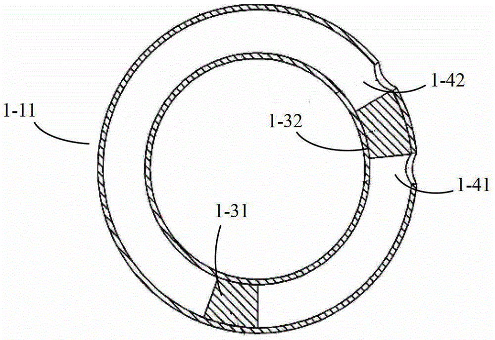
[0033] image 3 An embodiment of the annular compressor of the present invention is given, including an annular cavity 1, an annular stator yoke 2 with a tooth groove structure, the annular cavity 1 is located inside the annular stator yoke 2, the two are concentric, and there is no or only a small Clearance (within 3mm). The inner surface of the yoke 2 has a cogged structure, and a coil is wound on the cogged structure, and the coil is connected to an external power source. The slider 4 is located inside the annular cavity, the slider 4 is in close contact with the inside of the annular cavity, and can slide along the entire circumference of the inner wall of the annular cavity. The slider 4 is equipped with permanent magnets, so that at least one single magnetic pole or at least one pair of alternating magnetic poles are formed on its outer circumf...


PUM


Abstract

The invention discloses a ring compressor driven by a linear motor. The ring compressor comprises a ring cavity, a ring stator yoke, a coil, a sliding block and valves, wherein the ring stator yoke is sleeved outside the ring cavity, and the inner surface of the ring stator yoke has a tooth space structure; the coil is wound on the tooth space structure of the ring stator yoke; the sliding block is arranged in the ring cavity, and can slide along the inner wall of the cavity; and the valves are arranged in the ring cavity, and air ports are reserved in the wall surfaces of the ring cavity on the two sides of the valves respectively. Magnetic dispersion loss is reduced; the opendisconnecting of a core of the linear motor is avoided; moving components of the compressor and the motor are integrated, so that the ring compressor is simple and compact in structure, and has excellent frequency conversion characteristics, a good radiation effect, high power density and broad application prospect.

Description

technical field [0001] The invention belongs to the technical field of motors and compressors, in particular to a ring compressor. Background technique [0002] Compressor is a power-consuming fluid machine that upgrades low-pressure gas to high-pressure gas. It is widely used in occasions that require gas compression and driving, such as vapor compression refrigeration systems. It can also be applied to other fluid pumping or fluid oscillation occasions, such as regenerative refrigeration systems and other fluid compression drive systems. The compressed working medium is not limited to gas, but can also be liquid. [0003] Crank-connecting rod reciprocating piston compressors have a long history and are still widely used today. figure 1 It is a sectional view of a commonly used reciprocating piston compressor, which is mainly composed of motor stator 001, rotor 002, compressor cylinder 003, piston 004, crankshaft 005, connecting rod 006, etc. First, the motor stator 001 ...

Claims


Application Information

Patent Timeline
Patent Type & Authority Patents(China)
IPC IPC(8): F04B35/04F04B37/00F04B39/00F04B39/10
Inventor 张晓青李奎
Owner HUAZHONG UNIV OF SCI & TECH
Why Eureka
Try Eureka