Cross annular compressor

A crossover and compressor technology, applied in the field of compressors, can solve the problems of kinetic energy consumption, difficult to ensure positioning reliability, material fatigue, etc., and achieve the effect of reducing energy transmission loss, improving electromechanical conversion efficiency, and constant electromagnetic driving force

Active Publication Date: 2015-03-25
HUAZHONG UNIV OF SCI & TECH
View PDF6 Cites 0 Cited by
  • Summary
  • Abstract
  • Description
  • Claims
  • Application Information

AI Technical Summary

Problems solved by technology

However, it is difficult to ensure the reliability of positioning by exchanging the motion state of the slider through elastic collision
Frequent collisions cause noise, material fatigue, and consume kinetic energy reducing energy efficiency
This structure does not consider the effect of gas force on the stationary slider. In fact, the pressure difference between the high pressure side and the low pressure side will cause the stationary slider to be thrust in one direction and it is difficult to keep it still.
In addition, the structure does not give an operable driving method

Method used


Image

  • Cross annular compressor
  • Cross annular compressor
  • Cross annular compressor

Examples


Embodiment Construction

[0021] The present invention will be described in further detail below in conjunction with accompanying drawing and example.

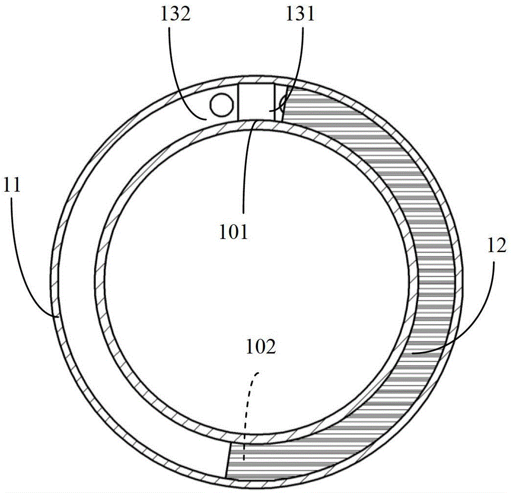
[0022] see image 3 , a ring of a cross-ring compressor, having a cavity 11 . The cavity 11 has a square section. There are openings 101 and 102 on the cavity as the interface between the cavity 11 and the cavity 21 . An exhaust port 131 and an air inlet 132 are arranged on the wall surface of the cavity 11 around the opening 101 . The slider 12 is located in the cavity 11 and can slide along the inner wall of the cavity 11 around.

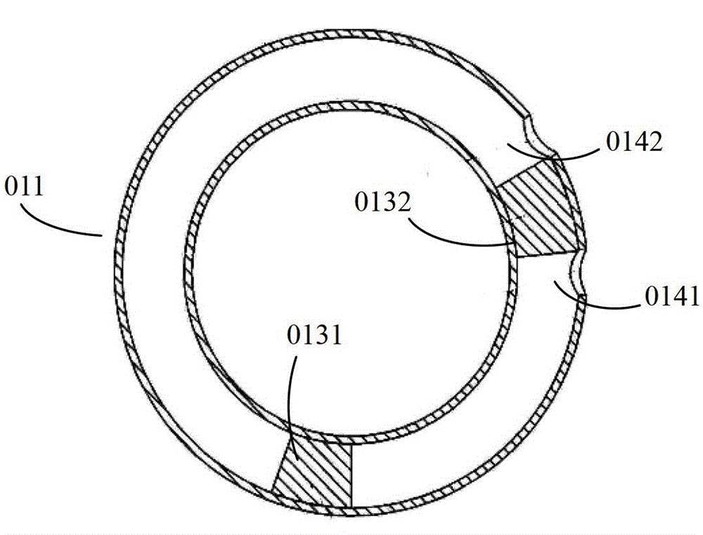
[0023] Such as Figure 4 As shown, the cross ring compressor consists of two image 3 The annular cavities shown are formed by orthogonal combination.

[0024] The annular cavity 11 needs to have sufficient mechanical strength (such as stainless steel), preferably a non-magnetic and non-conductive material (such as glass fiber reinforced plastics), so that it does not undergo plastic deformation when subjected to a p...


PUM


Abstract

The invention discloses a cross annular compressor which comprises two annular cavities and two sliding blocks, wherein the annular cavities are mutually orthogonal, and air inlets and air outlets are bilaterally and symmetrically formed in the same orthogonal side of the two annular cavities and the cavity walls of the annular cavities by using the orthogonal side as a center; the two sliding blocks are respectively positioned in the annular cavities; and in the process that the sliding block in the first annular cavity slides near the air inlet of the annular cavity, the sliding block in the second annular cavity passes through the intersection of two rings between the air inlet and the air outlet in the annular cavity, at the moment, the sliding block in the second annular cavity is used as a valve, the sliding block in the first annular cavity is used as a piston, and a compressing cavity is formed by the cavity with an exhaust port in the first annular cavity and between the piston and the valve. The cross annular compressor has the advantages of energy saving, high efficiency and simple and compact structure and has the characteristics of good frequency conversion, high efficiency and low vibration.

Description

technical field [0001] The invention belongs to the technical field of compressors, in particular to a cross ring compressor. Background technique [0002] Compressor is a power-consuming fluid machine that upgrades low-pressure gas to high-pressure gas. It is widely used in occasions that require gas compression and driving, such as vapor compression refrigeration systems. It can also be applied to other fluid pumping or fluid oscillation occasions, such as regenerative refrigeration systems and other fluid compression drive systems. The compressed working medium is not limited to gas, but can also be liquid. [0003] Reciprocating compressors have a long history and are still widely used today. figure 1 It is a sectional view of a commonly used reciprocating compressor, which is mainly composed of motor stator 001, rotor 002, compressor cylinder 003, piston 004, crankshaft 005, connecting rod 006, etc. First, the motor stator 001 forms a rotating magnetic field, interac...

Claims


Application Information

Patent Timeline
Patent Type & Authority Patents(China)
IPC IPC(8): F04B39/00
Inventor 张晓青李奎陈焕新
Owner HUAZHONG UNIV OF SCI & TECH
Why Eureka
Try Eureka