Magnetic closure system

a magnetic closure and magnetic technology, applied in the field of magnetic closure systems and closure systems, can solve the problems of unlimited potential and disclosed magnetic closure systems, and achieve the effect of dissuading misalignment upon closur

Active Publication Date: 2019-08-08
KLEIN KASSAB COOPER F
View PDF7 Cites 4 Cited by
  • Summary
  • Abstract
  • Description
  • Claims
  • Application Information

AI Technical Summary

Benefits of technology

[0009]The outwardly facing poles of the magnets on the first body may all be the same but opposite to the outwardly facing poles of the magnets on the second body. Alternatively, the outwardly facing poles of the magnets on both bodies may be reversed in a pattern that discourages misalignment upon closure.

Problems solved by technology

Indeed, the magnetic closure systems disclosed herein have unlimited potential as they may be applied universally for all types of material.

Method used


Image

  • Magnetic closure system
  • Magnetic closure system
  • Magnetic closure system

Examples


Embodiment Construction

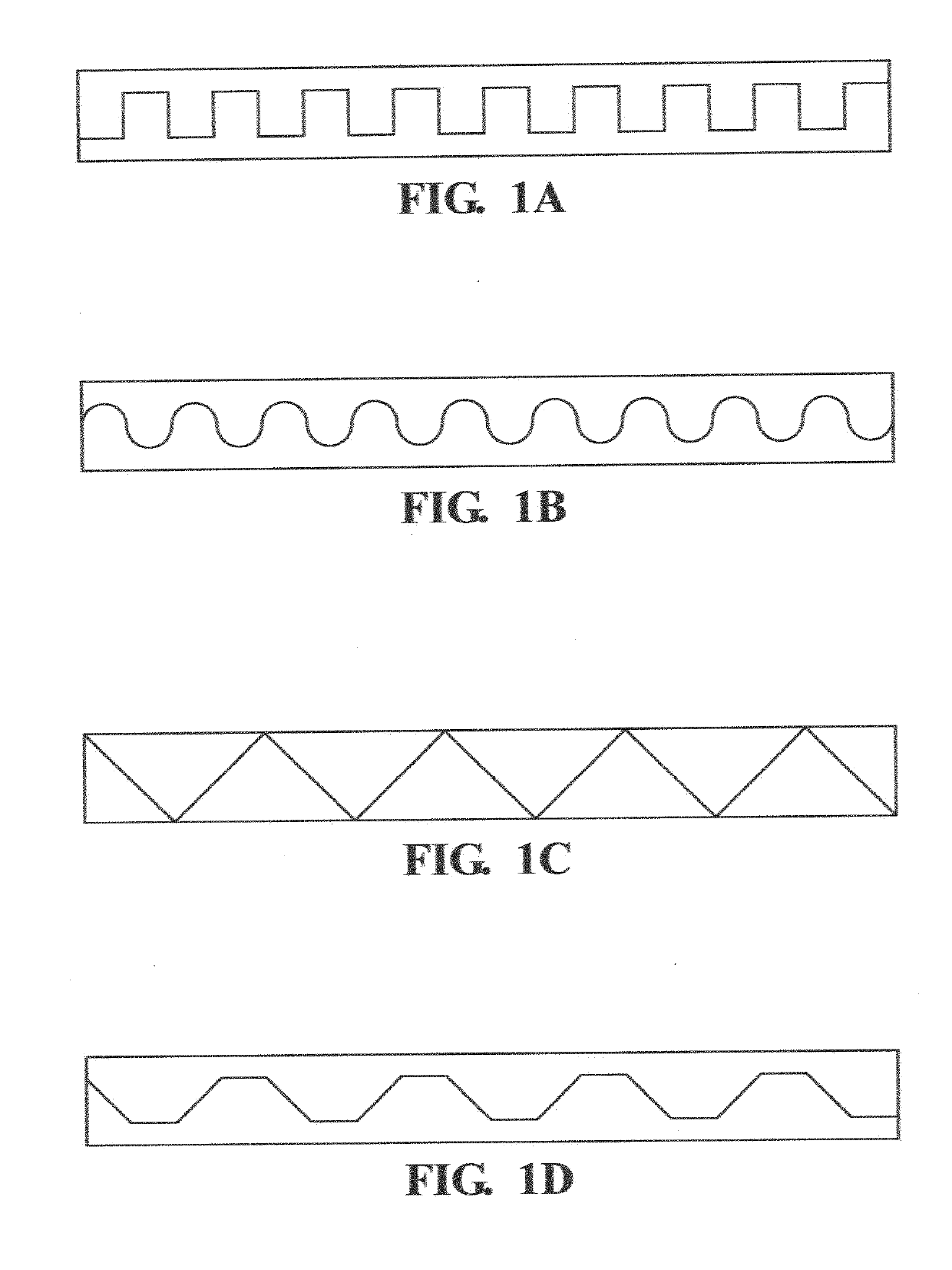
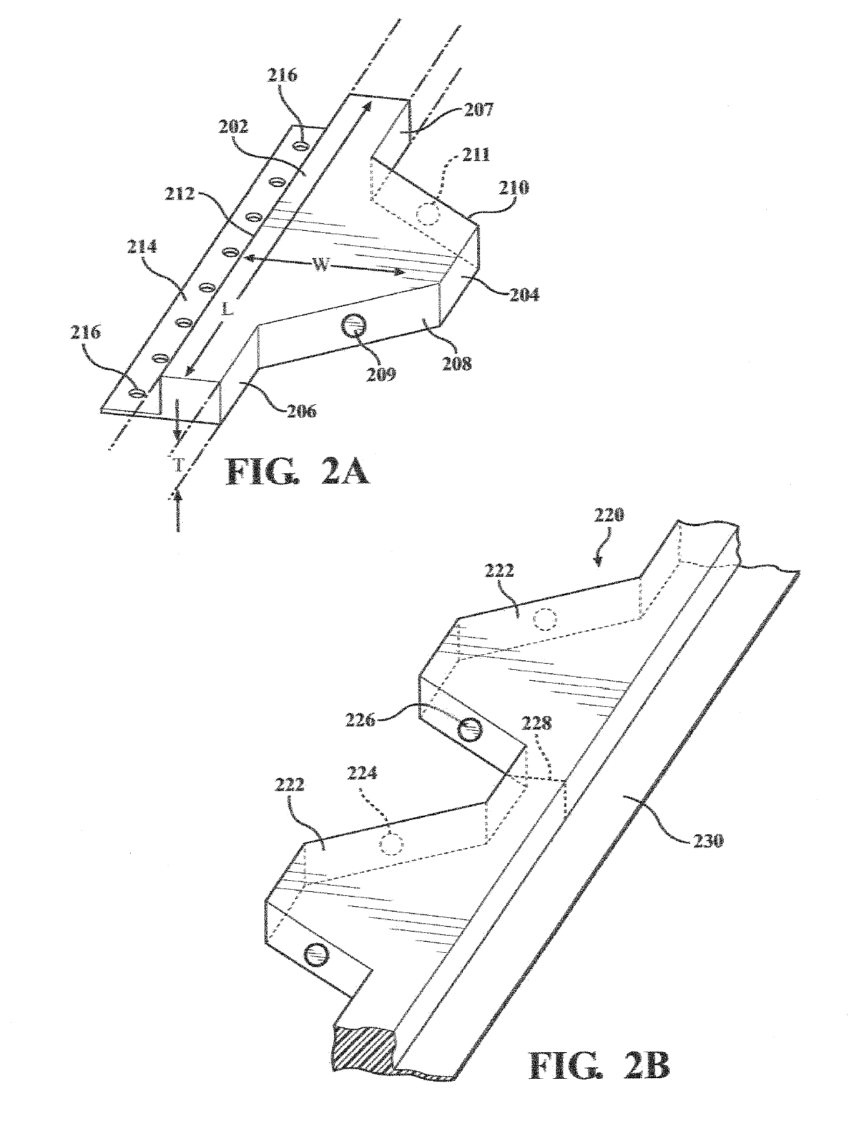
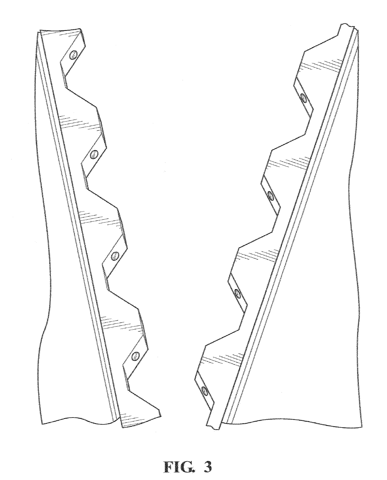
[0028]This invention is directed to a closure system wherein first and second opposing bodies with embedded magnets facilitate temporary attraction while allowing opening of the closure through reasonably applied manual opposed pulling. As used herein, the term “body” should be taken to include elongated strips, whether flexible, bendable, semi-rigid or rigid, as well as separate or individual units or cells that make up elongated structures. Each body has a profile (when viewed from the side) having peaks, troughs and slopes between the peaks and troughs. Permanent magnets are embedded within the slopes of the bodies, with the poles of the magnets being outwardly facing. The peaks on one side of the closure are received by the troughs of the side, such that the magnets on one side are attracted to the magnets of the other side to keep the bodies in contact until manually pulled apart.

[0029]Several different edge profiles are applicable to the invention, including square / rectangular...


PUM


Abstract

A magnetic closure system includes first and second opposing bodies with permanent magnets disposed on or in sloping surfaces of the bodies to keep the bodies in contact until being pulled apart. The bodies may be rigid, semi-rigid or flexible strips or elongated structures comprised of separate blocks, each block having two divergent sloping surfaces. Whether in strip or block form, each body may be adapted for attachment to a flexible material or fabric, such that the opposing bodies form a magnetic zipper. The magnetic closure system many be used in conjunction with many products, including clothing, curtains, bags, backpacks, purses, mats, tiles, or any other situation wherein materials or fabrics are joined.

Description

REFERENCE TO RELATED APPLICATIONS[0001]This application claims priority to, and the benefit of, U.S. Provisional Patent Application Ser. No. 62 / 628,262, filed Feb. 8, 2018, the entire content of which is incorporated herein by reference.FIELD OF THE INVENTION[0002]This invention relates generally to zippers and closure structures and, in particular, to a closure system and method that used permanent magnets disposed on or in repeating geometric shapes.BACKGROUND OF THE INVENTION[0003]Zippers present problems for many people on a daily basis. Getting dressed can be challenging and time-consuming. In many cases the zipper is difficult to latch at the base so that the teeth of the zipper align properly and the slider frequently gets stuck moving up or down. The slider that moves up and down often snags on the cloth around the zipper. As such, available zippers present a real challenge for many people, especially children, senior citizens, those with arthritis, and people who are physic...

Claims


Application Information

Patent Timeline
Patent Type & Authority Applications(United States)
IPC IPC(8): A41F1/00A44B19/26
CPCA41F1/002A44B19/267H01F7/0263A45C13/1069A44B19/16Y10T24/32A44D2203/00Y10T24/25
Inventor KLEIN-KASSAB, COOPER F.
Owner KLEIN KASSAB COOPER F
Why Eureka
Try Eureka