Arm adapted to be attached to a microscope, and microscope

a microscope and arm technology, applied in the field of microscopes, can solve the problems of time-consuming and cumbersome, and achieve the effects of less training, convenient use, and more time efficien

Active Publication Date: 2019-08-15
LEICA INSTR SINGAPORE PTE
View PDF0 Cites 2 Cited by
  • Summary
  • Abstract
  • Description
  • Claims
  • Application Information

AI Technical Summary

Benefits of technology

[0004]It is the object of the invention to provide a solution that is more time efficien

Problems solved by technology

This is however time-co

Method used


Image

  • Arm adapted to be attached to a microscope, and microscope
  • Arm adapted to be attached to a microscope, and microscope

Examples


Embodiment Construction

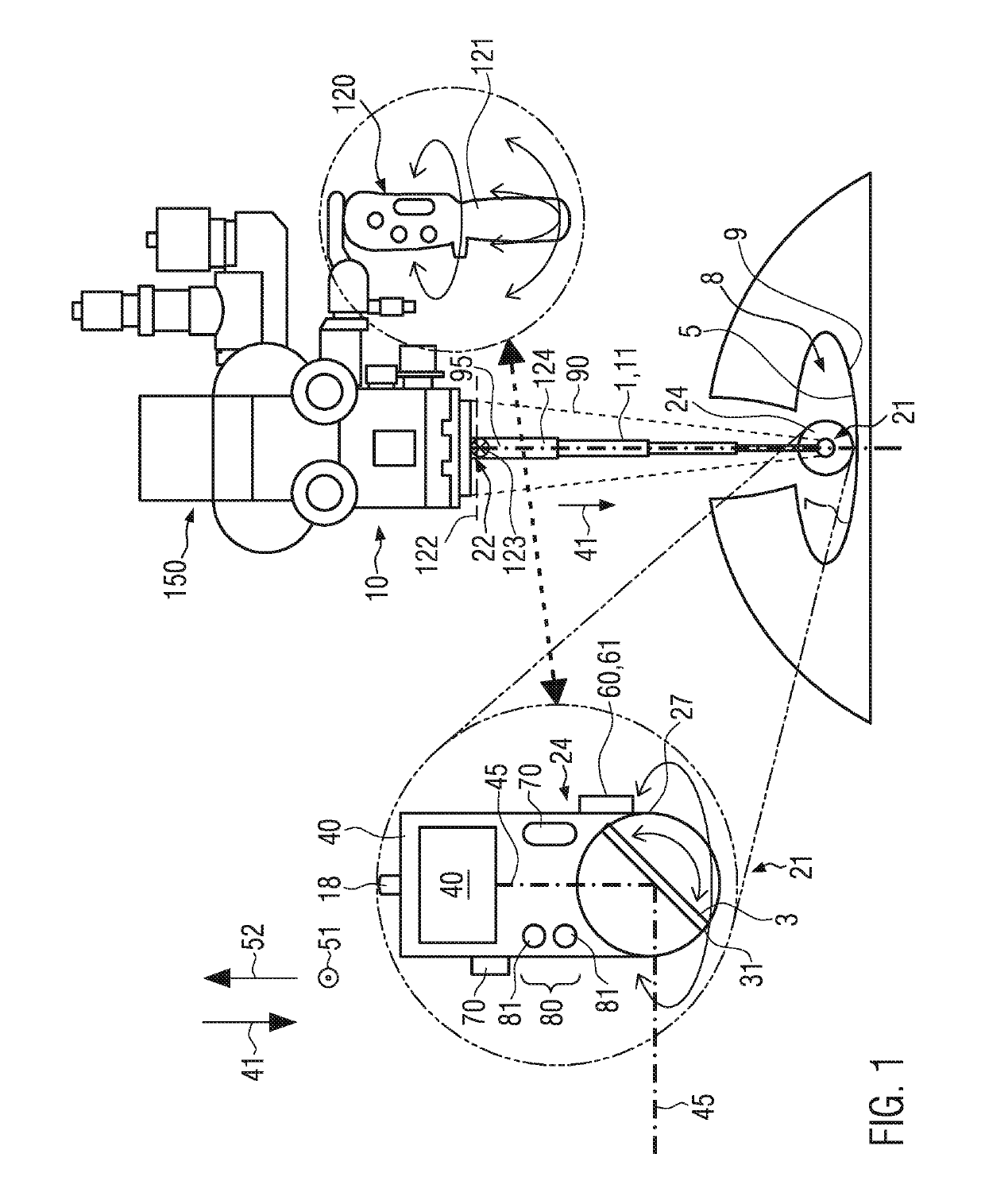
[0073]In FIG. 1, an arm 1 is attached to a microscope 10. The microscope 10 is used as a surgical microscope 10 to inspect an operation area 5, for example inside a human head during brain surgery. The operation area 5 is in direct line of sight of optics of the microscope 10. However, for the surgeon it is also important to be able to look at a neighboring area 9 next to the operation area 5. Conventionally, the microscope is removed and an endoscope is used to look at the neighboring area 9. However, due to the inventive solution, it is possible to look at the neighboring area 9 without removing the microscope 10.

[0074]The arm 1 comprises at a distal end 21 that is opposite a proximal end 22 at which the arm 1 is attached to the microscope 10, a light beam deflection member 3 that is rotatable around at least one axis 51, 52. In the embodiment of FIG. 1, the rotatable light beam deflection member 3 is rotatable around two axes 51, 52, one of which is parallel to an extension direc...


PUM


Abstract

The invention relates to an arm (1) adapted to be attached to a microscope (10), in particular a surgical microscope (10), wherein the arm (1) comprises at a distal end (21) a light beam deflection member (3) or a camera. An inventive microscope (10) comprises an arm (1).

Description

CROSS REFERENCE TO RELATED APPLICATIONS[0001]This application claims priority of European patent application number 18156144.0 filed Feb. 9, 2018, the entire disclosure of which is incorporated by reference herein.FIELD OF THE INVENTION[0002]The invention relates to the field of microscopes, in particular surgical microscopes.BACKGROUND OF THE INVENTION[0003]Such microscopes are often used to inspect the operation area at which surgery is performed. In many cases, it is necessary to not only have an overview of the operation area but also of the neighboring area, for example of a cavity in which surgery takes place. In current solutions, the microscope is removed from the operation area and an endoscope is used in its stead to get an overview. This is however time-consuming and cumbersome.SUMMARY OF THE INVENTION[0004]It is the object of the invention to provide a solution that is more time efficient, easy to use, more intuitive, requires very little or no training, and could be saf...

Claims


Application Information

Patent Timeline
IPC IPC(8): G02B21/00G02B21/06A61B90/20A61B90/00
CPCG02B21/0012G02B21/06A61B90/20A61B90/361A61B90/37G02B21/362G02B21/361G02B21/22G02B26/105A61B2017/00123A61B90/50A61B2090/371A61B2090/367G02B21/00
Inventor THEMELIS, GEORGE
Owner LEICA INSTR SINGAPORE PTE
Why Eureka
Try Eureka