
Realtime lens aberration correction from eye tracking

a technology of real-time lens and aberration correction, which is applied in the field of real-time lens aberration correction from eye tracking, can solve the problems of deteriorating the quality of the image viewed by a user and the image viewed by the user through the optics may be of lower quality, and achieve the effect of removing aberration

Active Publication Date: 2019-08-15
SONY INTERACTIVE ENTERTAINMENT INC
View PDF0 Cites 10 Cited by
  • Summary
  • Abstract
  • Description
  • Claims
  • Application Information

AI Technical Summary

Benefits of technology

The invention relates to systems and methods for improving the quality of images created by applications and viewed through head mounted displays (HMDs). These systems adjust the image quality to compensate for distortions caused by the user's eye alignment with the optics of the HMD. By identifying the alignment offset of the user's eye and adjusting the pre-distorted image provided by the application, the result is a corrected, pre-distorted image that removes any aberration caused by the misalignment of the eye with the HMD's optics. The technical effect of this patent is to provide a high-quality image for viewing through HMDs, enhancing the viewing experience for users.

Problems solved by technology

However, these optics produce aberrations (geometric and / or chromatic) that results in the deterioration of the quality of the image viewed by a user.
However, the image viewed by the user through the optics may be of lower quality due to aberrations, such as chromatic aberrations and / or geometric aberrations, caused by misalignment of the user's eye(s) with the optical axis of the lens of the optics provided in the HMD.

Method used


Image

  • Realtime lens aberration correction from eye tracking
  • Realtime lens aberration correction from eye tracking
  • Realtime lens aberration correction from eye tracking

Examples


Embodiment Construction

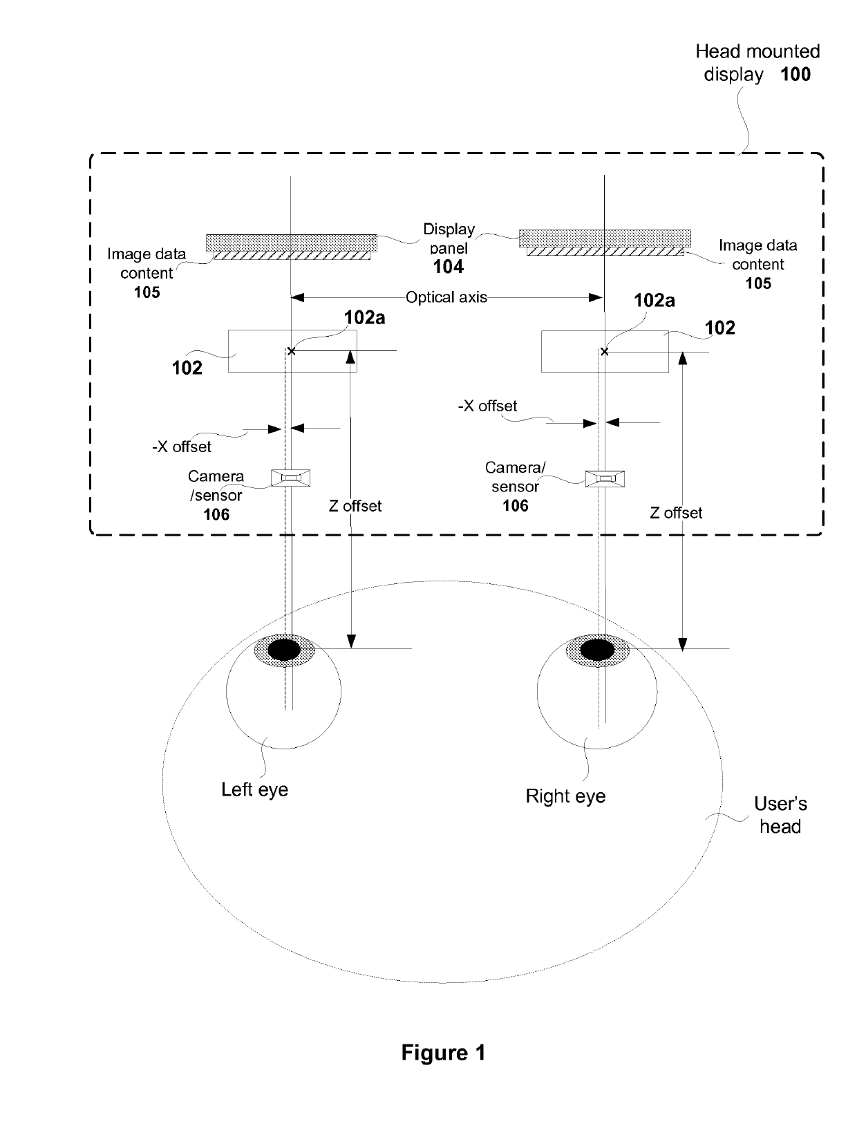
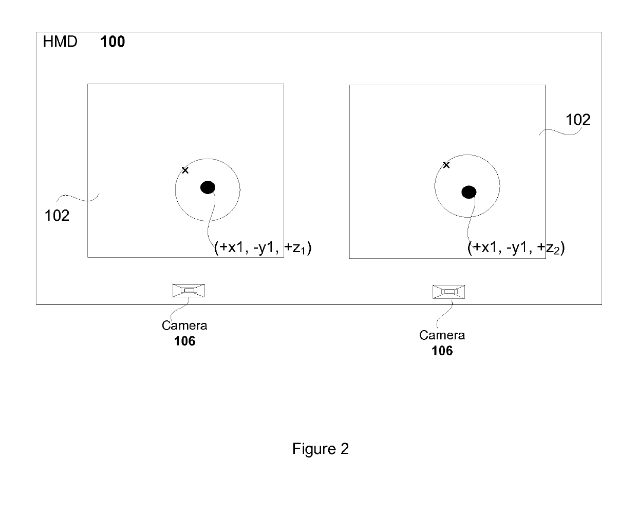
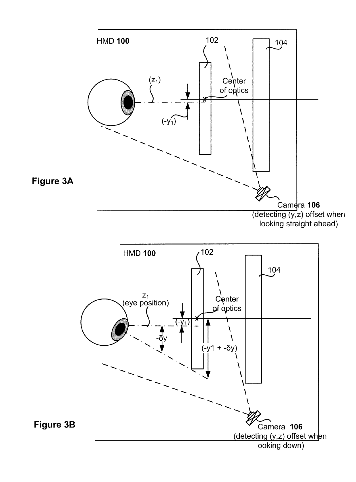
[0036]Systems and methods for determining alignment offset and using the alignment offset for adjusting an image received from an application, are described. An application, such as a gaming application, executing on a computing device / console or game cloud causes images of interactive scenes of the game to be transmitted to a head mounted display (HMD) for rendering on a display screen of the HMD. The image that is transmitted is pre-distorted. The pre-distorted image is processed by optics of the HMD for near-eye view, such that when the image is viewed through the lens of the optics, the image is in-focus. The amount of pre-distortion that is applied to the image is dependent on the distance of the eye from the lens of the optics provided in the HMD. Additionally, in order to provide a clear image, alignment of the eye(s) of the user has to match the optical axis of at least one lens of optics provided in the HMD. The eye(s) of the user wearing the HMD may not be completely align...


PUM


Abstract

Systems and methods include receiving an image for presenting on a display screen of a head mounted display (HMD). The image is provided by an application. The received image is pre-distorted to enable optics provided in a HMD to render the image. An alignment offset is identified for an eye of a user wearing the HMD by determining a position of the eye relative to an optical axis of at least one lens of the optics of the HMD. The pre-distorted image provided by the application is adjusted to define a corrected pre-distorted image that accounts for the alignment offset. The corrected pre-distorted image is forwarded to the display screen of the HMD for rendering, such that the image presented through the optics of the HMD removes aberrations caused by the alignment offset.

Description

CLAIM OF PRIORITY[0001]This application is a continuation of and claims priority under 35 U.S.C. § 120 to U.S. patent application Ser. No. 14 / 835,558, filed on Aug. 25, 2015, and entitled, “REALTIME LENS ABERRATION CORRECTION FROM EYE TRACKING,” which claims priority under 35 U.S.C. § 119 to U.S. Provisional Patent Application No. 62 / 058,057, filed on Sep. 30, 2014, and entitled “REALTIME LENS ABERRATION CORRECTION FROM EYE TRACKING”, which are incorporated herein by reference in their entirety.CROSS REFERENCE TO RELATED APPLICATIONS[0002]This application is related to U.S. application Ser. No. 14 / 187,127, filed on Feb. 21, 2014, and entitled “DIGITAL INTER-PUPILLARY DISTANCE ADJUSTMENT,” U.S. application Ser. No. 14 / 225,408, filed on Mar. 25, 2014, and entitled “SYSTEMS AND METHODS FOR CUSTOMIZING OPTICAL REPRESENTATION OF VIEWS PROVIDED BY A HEAD MOUNTED DISPLAY BASED ON OPTICAL PRESCRIPTION OF A USER,” and United Kingdom patent application No. 1410397.2 filed on Jun. 11, 2014, wh...

Claims


Application Information

Patent Timeline
Patent Type & Authority Applications(United States)
IPC IPC(8): G02B27/01G02B27/00
CPCG02B27/0172G02B27/0068G02B27/0093G02B2027/014G02B2027/011G02B2027/0138G02B2027/0187
Inventor STAFFORD, JEFFREY ROGERLARSEN, ERIC
Owner SONY INTERACTIVE ENTERTAINMENT INC
Learn More