Liquid crystal display device

a liquid crystal display and display device technology, applied in non-linear optics, instruments, optics, etc., can solve the problems of low aperture ratio, reduce the transmittance at the end of the slit, and reduce the aperture ratio of the pixel

Active Publication Date: 2019-08-29
PANASONIC INTELLECTUAL PROPERTY CORP OF AMERICA
View PDF4 Cites 2 Cited by
  • Summary
  • Abstract
  • Description
  • Claims
  • Application Information

AI Technical Summary

Benefits of technology

[0005]In the above configuration, there is a problem in that an aperture ratio is low. That is, in the conventional configuration, an electric field is hardly applied to liquid crystal disposed at an end of the slit, and transmittance at the end of the slit is decreased. Because the end of the slit is disposed in a long-side region of the pixel electrode, the aperture ratio of the pixel is decreased as a whole.
[0006]The present disclosure has been made in view of the above problem, and an object of the present disclosure is to improve the aperture ratio in the lateral electric field system liquid crystal display device.
[0007]To solve the above problem, a liquid crystal display device according to a present disclosure comprises: a first data line extending in a first direction; a first pixel electrode and a second pixel electrode that are arranged in the first direction; a first transistor connected to the first pixel electrode; a second transistor connected to the second pixel electrode; and a first gate line electrically connected to the first transistor and the second transistor, wherein in the first pixel electrode, a first length along the first direction is shorter than a second length along a second direction perpendicular to the first direction, and the first pixel electrode includes at least one slit, and the slit extends at an angle of less than or equal to 45 degrees with respect to the second direction. The liquid crystal display device according to the present disclosure can improve the aperture ratio in the lateral electric field system liquid crystal display device.

Problems solved by technology

In the above configuration, there is a problem in that an aperture ratio is low.

Method used


Image

  • Liquid crystal display device
  • Liquid crystal display device
  • Liquid crystal display device

Examples


first exemplary embodiment

[0015]A first exemplary embodiment of the present disclosure will be described below with reference to the drawings.

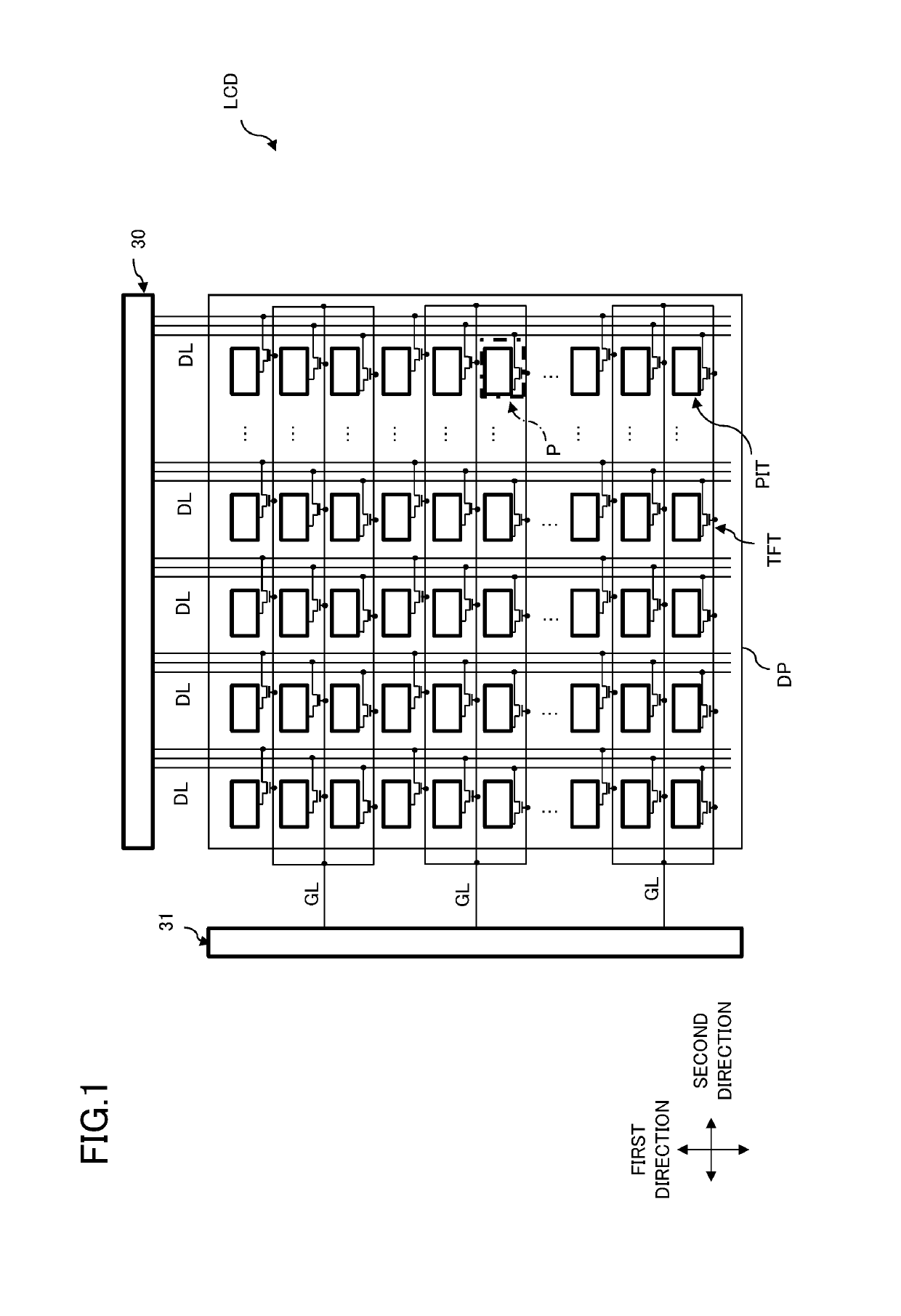
[0016]FIG. 1 is a plan view illustrating an overall configuration of liquid crystal display device LCD according to the first exemplary embodiment of the present disclosure. Liquid crystal display device LCD includes display panel DP that displays an image, a display panel drive circuit (data line drive circuit 30, gate line drive circuit 31) that drives display panel DP, a control circuit (not illustrated) that controls the display panel drive circuit, and a backlight (not illustrated) that irradiates display panel DP with backlight light from a rear surface side.

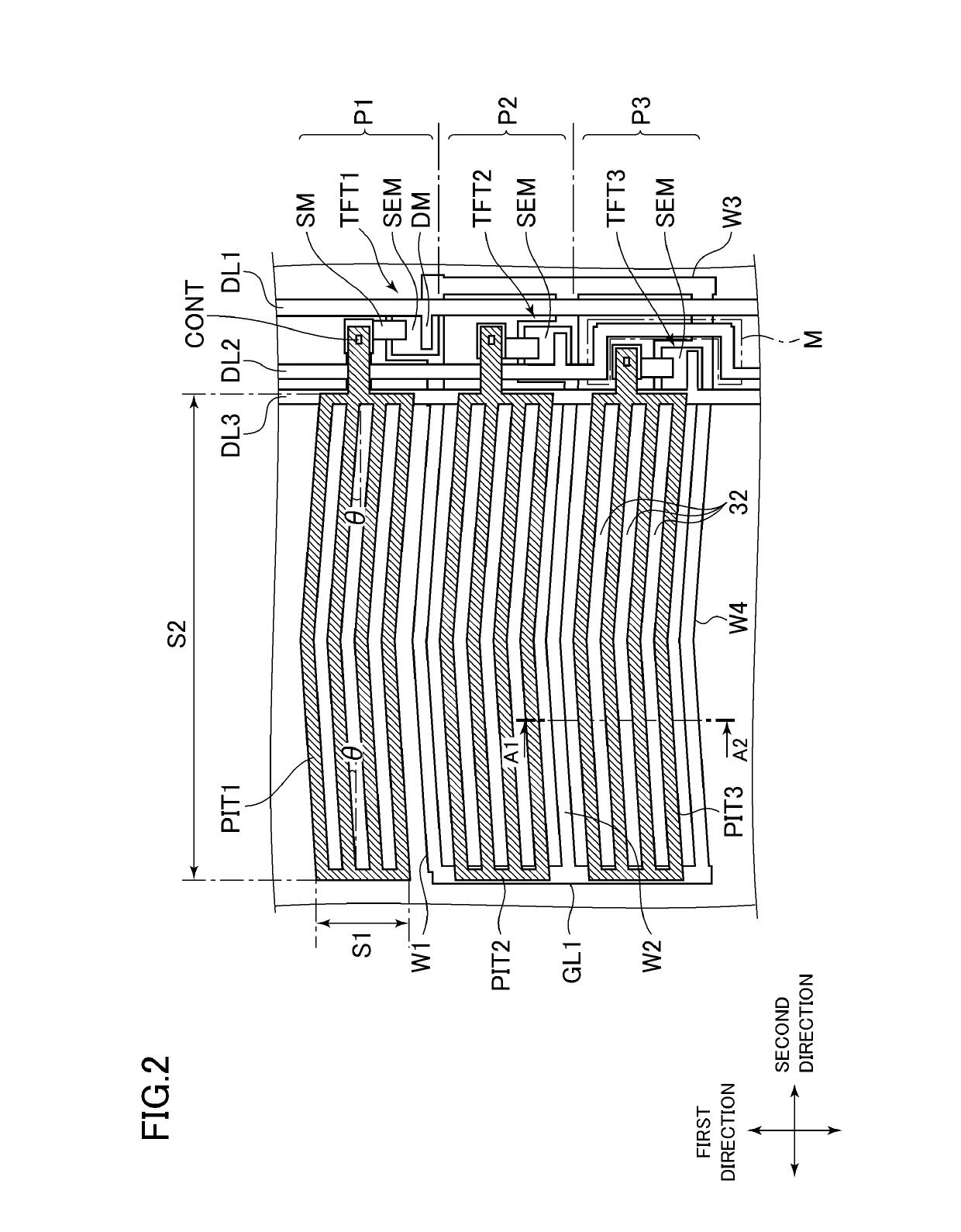
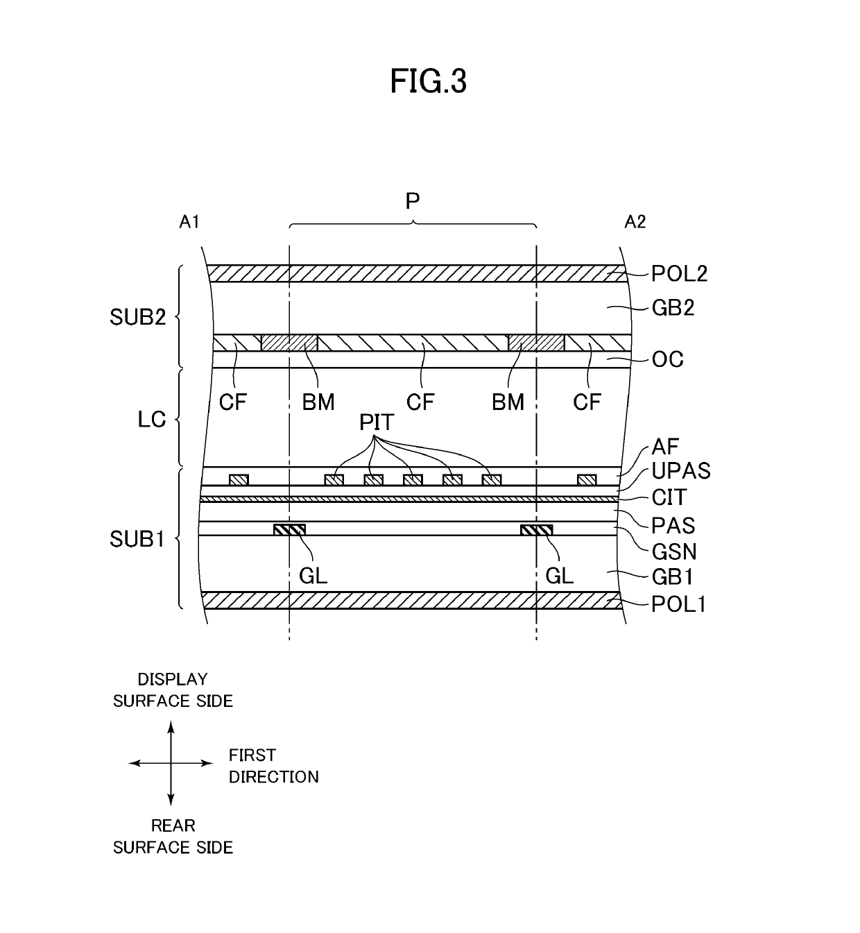
[0017]FIG. 2 is a plan view illustrating a configuration of a part of display panel DP of the first exemplary embodiment. FIG. 3 is an end face view of a cut portion taken along line A1-A2 in FIG. 2. Three pixels P are illustrated in FIG. 2, and one pixel P is illustrated in FIG. 3.

[0018]Display panel DP incl...

second exemplary embodiment

[0036]A second exemplary embodiment will be described below with reference to the drawings. The description of the same configuration as that of the first exemplary embodiment will be omitted.

[0037]FIG. 4 is a plan view illustrating a configuration of a part of display panel DP of the second exemplary embodiment. FIG. 5 is a plan view illustrating a schematic configuration of liquid crystal display device LCD of the second exemplary embodiment.

[0038]As illustrated in FIGS. 4 and 5, in the second exemplary embodiment, first data line DL1, second data line DL2, and third data line DL3, which extend in the first direction are formed in TFT substrate SUB1. Second data line DL2 is disposed between first data line DL1 and third data line DL3. First pixel electrode PIT1, second pixel electrode PIT2, and third pixel electrode PIT3 are arranged in the first direction, and third pixel electrode PIT3 is disposed between first pixel electrode PIT1 and second pixel electrode PIT2. That is, third...

third exemplary embodiment

[0049]A third exemplary embodiment will be described below with reference to the drawings. The description of the same configuration as those of the first and second exemplary embodiments will be omitted.

[0050]FIG. 6 is a plan view illustrating a configuration of a part of display panel DP of the third exemplary embodiment. FIG. 7 is a plan view illustrating a schematic configuration of liquid crystal display device LCD of the third exemplary embodiment.

[0051]As illustrated in FIGS. 6 and 7, in the third exemplary embodiment, first data line DL1 and second data line DL2, which extend in the first direction, are formed in TFT substrate SUB1. First pixel electrode PIT1, second pixel electrode PIT2, third pixel electrode PIT3, fourth pixel electrode PIT4, fifth pixel electrode PIT5, and sixth pixel electrode PIT6 are sequentially arranged in the first direction. That is, second pixel electrode PIT2 is disposed between first pixel electrode PIT1 and third pixel electrode PIT3, and is ad...


PUM

PropertyMeasurementUnit
angleaaaaaaaaaa
angleaaaaaaaaaa
acute angleaaaaaaaaaa

Abstract

A liquid crystal display device comprises: a first data line extending in a first direction; a first pixel electrode and a second pixel electrode that are arranged in the first direction; a first transistor connected to the first pixel electrode; a second transistor connected to the second pixel electrode; and a first gate line electrically connected to the first transistor and the second transistor, wherein in the first pixel electrode, a first length along the first direction is shorter than a second length along a second direction perpendicular to the first direction, and the first pixel electrode includes at least one slit, and the slit extends at an angle of less than or equal to 45 degrees with respect to the second direction.

Description

CROSS-REFERENCE TO RELATED APPLICATION[0001]This application claims priority from Japanese application JP 2018-030565, filed Feb. 23, 2018. This Japanese application is incorporated herein by reference.BACKGROUND1. Technical Field[0002]The present disclosure relates to a liquid crystal display device.2. Description of the Related Art[0003]In various liquid crystal display devices, a lateral electric field system liquid crystal display device has an advantage of an excellent wide viewing angle characteristic. For example, the lateral electric field system liquid crystal display device includes a pixel electrode and a common electrode in one of a pair of substrates, which are disposed opposite each other with a liquid crystal layer interposed between the pair of substrates. An electric field (lateral electric field) in a direction parallel to a substrate surface is generated between the pixel electrode and the common electrode, and the lateral electric field is applied to liquid cryst...

Claims


Application Information

Patent Timeline
Patent Type & Authority Applications(United States)
IPC IPC(8): G02F1/1343G02F1/1362G02F1/137G02F1/1337
CPCG02F1/134336G02F1/136286G02F1/137G02F1/1337G02F2001/133738G02F2201/123G02F2201/40G02F1/1368G02F1/133514G02F2001/13706G02F2201/122G02F1/134363G02F1/133738G02F1/13706
Inventor KAWAMURA, TETSUYA
Owner PANASONIC INTELLECTUAL PROPERTY CORP OF AMERICA
Why Eureka
Try Eureka