
Signaling individualized transmission duration threshold for rts/cts

a transmission duration and rts technology, applied in the field of network communication, can solve the problems of inability to customize the transmission duration of rts/cts for individual stas, no packet can pass through, and the dense communication environment is prone to this hidden node problem, so as to enhance the spectral usage efficiency of the network

Active Publication Date: 2019-09-05
MEDIATEK SINGAPORE PTE LTD SINGAPORE
View PDF0 Cites 2 Cited by
  • Summary
  • Abstract
  • Description
  • Claims
  • Application Information

AI Technical Summary

Benefits of technology

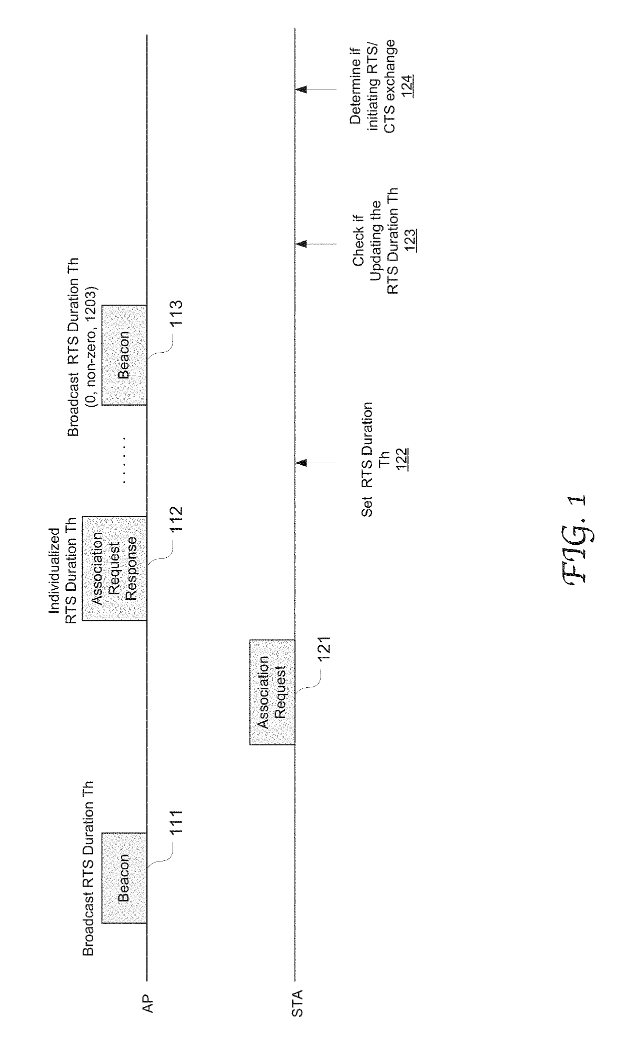
This patent provides effective communication protocols to improve spectrum usage efficiency in a wireless local area network (WLAN) by enabling flexible assignments of varying transmission opportunity (TXOP) duration thresholds to individual stations (STAs). The access point (AP) can individually signal each associated STA with regard to an RTS / CTS TXOP duration threshold based on suitable factors such as classification, interference level, and hidden node problem. This results in flexibility and specific control over RTS / CTS usage by individual STAs, leading to improved spectrum usage efficiency and interference mitigation.

Problems solved by technology

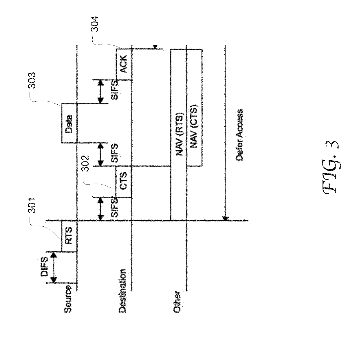
In a wireless network, a hidden node problem refers to the situation in which a node can communicate with a second node, (e.g., a wireless access point (AP)) but cannot directly communicate with other nodes that are communicating with the second node.
This leads to difficulties in the media access control sub-layer since multiple nodes may send data packets to the second node simultaneously, causing interference at the second node such that neither packet can get through.
A dense communication environment is prone to this hidden node problem.
Therefore, the usage of RTS / CTS transmission cannot be customized for individual STAs.

Method used


Image

  • Signaling individualized transmission duration threshold for rts/cts
  • Signaling individualized transmission duration threshold for rts/cts
  • Signaling individualized transmission duration threshold for rts/cts

Examples


Embodiment Construction

[0020]Reference will now be made in detail to the preferred embodiments of the present invention, examples of which are illustrated in the accompanying drawings. While the invention will be described in conjunction with the preferred embodiments, it will be understood that they are not intended to limit the invention to these embodiments. On the contrary, the invention is intended to cover alternatives, modifications, and equivalents which may be included within the spirit and scope of the invention as defined by the appended claims. Furthermore, in the following detailed description of embodiments of the present invention, numerous specific details are set forth in order to provide a thorough understanding of the present invention. However, it will be recognized by one of ordinary skill in the art that the present invention may be practiced without these specific details. In other instances, well-known methods, procedures, components, and circuits have not been described in detail ...


PUM


Abstract

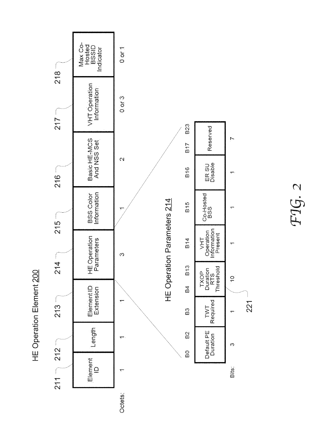
System and method of using an AP to individually controlling RTS / CTS duration thresholds for multiple STAs in a WLAN. In response to a STA's association request, the AP determines a duration threshold specific to the STA and encloses this information in an association response for transmission to the STA. By using a broadcast frame, the AP may instruct multiple STAs to uniformly update their stored duration thresholds. For example, if the duration threshold field in the beacon frame is set to 0, the multiple STAs preserve their current duration thresholds; if the field is set to a non-zero value less than 1023, the multiple STAs all update their duration thresholds to the non-zero value; if this field is set to 1023, the multiple STAs disable the RTS / CTS transmissions based on the duration threshold. Based on a current threshold and pertinent policies, an STA can decide whether to initiate an RTS / CTS transmission sequence.

Description

CROSS REFERENCE TO RELATED APPLICATION[0001]This patent application claims priority and benefit of the U.S. Provisional Patent Application No. 62 / 637,420, entitled “HE DURATION-BASED RTS,” filed on Mar. 2, 2018, the entire content of which is herein incorporated by reference for all purposes.TECHNICAL FIELD[0002]Embodiments of the present disclosure relate generally to the field of network communication, and more specifically, to the field of communication protocols used in wireless communication.BACKGROUND OF THE INVENTION[0003]In a wireless network, a hidden node problem refers to the situation in which a node can communicate with a second node, (e.g., a wireless access point (AP)) but cannot directly communicate with other nodes that are communicating with the second node. This leads to difficulties in the media access control sub-layer since multiple nodes may send data packets to the second node simultaneously, causing interference at the second node such that neither packet ca...

Claims


Application Information

Patent Timeline
Patent Type & Authority Applications(United States)
IPC IPC(8): H04W74/08H04W74/00H04W76/14H04W88/08H04W72/12
CPCH04W74/0816H04W74/002H04W84/12H04W88/08H04W72/1263H04W76/14H04W76/12
Inventor SEOK, YONGHOWANG, CHAO-CHUNYEE, JAMES CHIH-SHI
Owner MEDIATEK SINGAPORE PTE LTD SINGAPORE
Learn More