Eureka AIR delivers breakthrough ideas for toughest innovation challenges, trusted by R&D personnel around the world.

Leather bicycle saddle

a saddle and leather technology, applied in the field of saddles, can solve the problems of limiting the application of bicycle saddles, insufficient tension of leather bicycle saddles, and the rider to feel uncomfortable, and achieve the effect of improving riding comfort and good cushioning

Active Publication Date: 2017-10-19
HSU CHUNG YING +2
View PDF0 Cites 1 Cited by
  • Summary
  • Abstract
  • Description
  • Claims
  • Application Information

AI Technical Summary

Benefits of technology

The present invention is a leather bicycle saddle that provides better cushioning, comfort, and reduces noise during riding. It achieves this by having an adjustment seat that can be rotated forward from a horizontal to an inclined position. This allows the leather cover of the saddle to act like a spring or sponge, reducing the impact between the rider's buttocks and the saddle. The design also prevents the generation of noises and allows quick adjustment of the tension of the leather cover for optimal flex.

Problems solved by technology

A leather bicycle saddle has a better texture and looking, however, because a leather bicycle saddle has no sponge or any other flexible material stuffed therein for cushioning, the leather cover will accurately transfer ground reaction forces to the buttocks of the bicycle rider, causing the bicycle rider to feel uncomfortable, and therefore, a leather bicycle saddle is not suitable for use in a mounting bike for off-road cycling, greatly limiting its applications.
Further, the tension of a leather bicycle saddle will become insufficient after a long use, causing the leather cover of the leather bicycle saddle to get depressed.
However, according to this prior art design, the tension of the leather cover will be slightly lowered after a long use of the leather bicycle saddle, at this time, the metal part of the arc support of the leather bicycle saddle and the metal screw sleeve that receives the adjustment screw bolt will be forced to continuously rub against each other as the bicycle rider shifts the center of gravity of the body during riding, producing disturbing noises.

Method used


Image

  • Leather bicycle saddle
  • Leather bicycle saddle
  • Leather bicycle saddle

Examples


Embodiment Construction

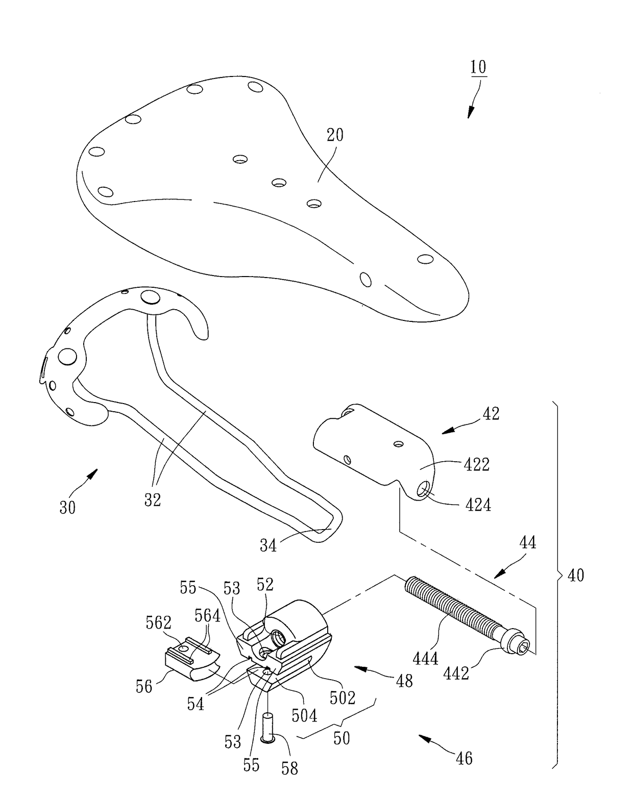
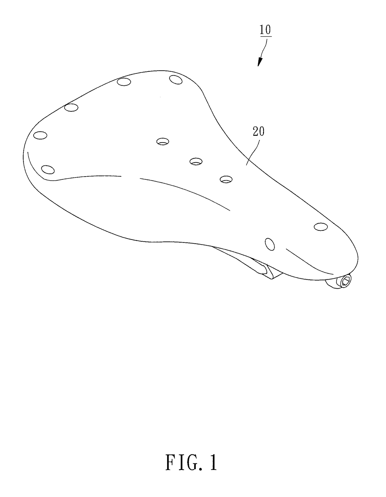
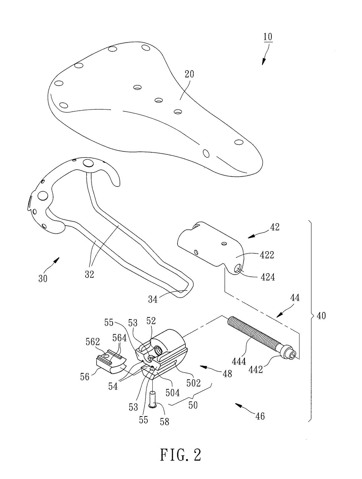
[0018]Referring to FIGS. 1 and 2, a leather bicycle saddle 10 in accordance with a first embodiment of the present invention is shown. The leather bicycle saddle 10 comprises a leather cover 20, an arc support 30 and an adjustment device 40.

[0019]The arc support 30 is mounted at a bottom side of the leather cover 20, comprising two opposing support rods 32. The two support rods 32 have respective front ends thereof connected to each other to form a head abutment portion 34, and respective rear ends thereof affixed to a rear side of the leather cover 20.

[0020]The adjustment device 40 is mounted at the bottom side of the leather cover 20, comprising a screw bolt holder 42, an adjustment screw bolt 44, and an adjustment seat 46. As illustrated in FIGS. 2 and 3, the screw bolt holder 42 is affixed to a front bottom side of the leather cover 20 by, for example, riveting. The screw bolt holder 42 comprises a stop wall 422 and a through hole 424 cut through the stop wall 422. The adjustmen...


PUM


Abstract

A leather bicycle saddle includes a leather cover, an arc support supporting the leather cover and having a front end terminating in a head abutment portion and a rear end affixed to a rear bottom side of the leather cover, and an adjustment device including a screw bolt holder affixed to a front bottom side of the leather cover, an adjustment screw bolt abutted against the screw bolt holder. The adjustment seat includes a seat block defining a mounting slot and a screw hole, and a stop block. The stop block is engaged into the open end of the mounting slot and stopped at the head abutment portion of the arc support against the close end of the mounting slot. The screw hole of the seat block receives the adjustment screw bolt.

Description

BACKGROUND OF THE INVENTION1. Field of the Invention[0001]The present invention relates to bicycle saddles and more particularly, to a leather bicycle saddle.2. Description of the Related Art[0002]The covers of commercial bicycle saddles are mainly selected from the group of polyurethane and leathers. A bicycle saddle using a polyurethane cover generally has sponge or other elastic stuffing material (such as silicon rubber) stuffed therein to enhance the cushioning and shock absorbing effects. Bicycle saddles of this kind are suitable for use in different types of bikes. A leather bicycle saddle generally comprises a leather cover, an arc support for supporting the leather cover, and an adjustment and connection mechanism provided between the leather cover and the arc support. A leather bicycle saddle has a better texture and looking, however, because a leather bicycle saddle has no sponge or any other flexible material stuffed therein for cushioning, the leather cover will accurate...

Claims


Application Information

Patent Timeline
Patent Type & Authority Applications(United States)
IPC IPC(8): B62J1/10B62J1/08B62J1/18
CPCB62J1/10B62J2700/634B62J1/18B62J1/08B62J1/00
Inventor HSU, CHUNG-YINGLAI, CHIEN-SHUNLEE, CHIA-WEN
Owner HSU CHUNG YING
Why Eureka
Eureka Blog
Learn More