Disengagement mechanism for boring bar apparatus

Active Publication Date: 2019-09-12
BORE REPAIR SYST
View PDF0 Cites 1 Cited by
  • Summary
  • Abstract
  • Description
  • Claims
  • Application Information

AI Technical Summary

Benefits of technology

The present patent relates to various methods for joining boring bars together, creating a secure and unchanged outer diameter. Additionally, the patent allows for easy modification of the overall length of the feed screw assembly by interchangeable shafts, as well as a drive interrupt to prevent further feeding of the boring bar. The patent also provides a thread engagement / disengagement mechanism that allows for easy shifting of the feed coupling and the connected boring bar to a new desired relative position without the need for actuating the drive motor or rotating manually the feed screw.

Problems solved by technology

One of the most commonly required repairs for large machinery or equipment is the repair or refurbishing of a bore, that is, a circular opening that supports an axle or a shaft, for example, as these circular openings eventually become damaged or worn due to a variety of reasons, including mechanical wear of the parts, thereby resulting in a need to restructure or reconstruct the bore to the proper diameter and shape.

Method used


Image

  • Disengagement mechanism for boring bar apparatus
  • Disengagement mechanism for boring bar apparatus
  • Disengagement mechanism for boring bar apparatus

Examples


Embodiment Construction

[0032]The present invention will be understood by reference to the following detailed description, which should be read in conjunction with the appended drawings. It is to be appreciated that the following detailed description of various embodiments is by way of example only and is not meant to limit in any way, the scope of the present invention.

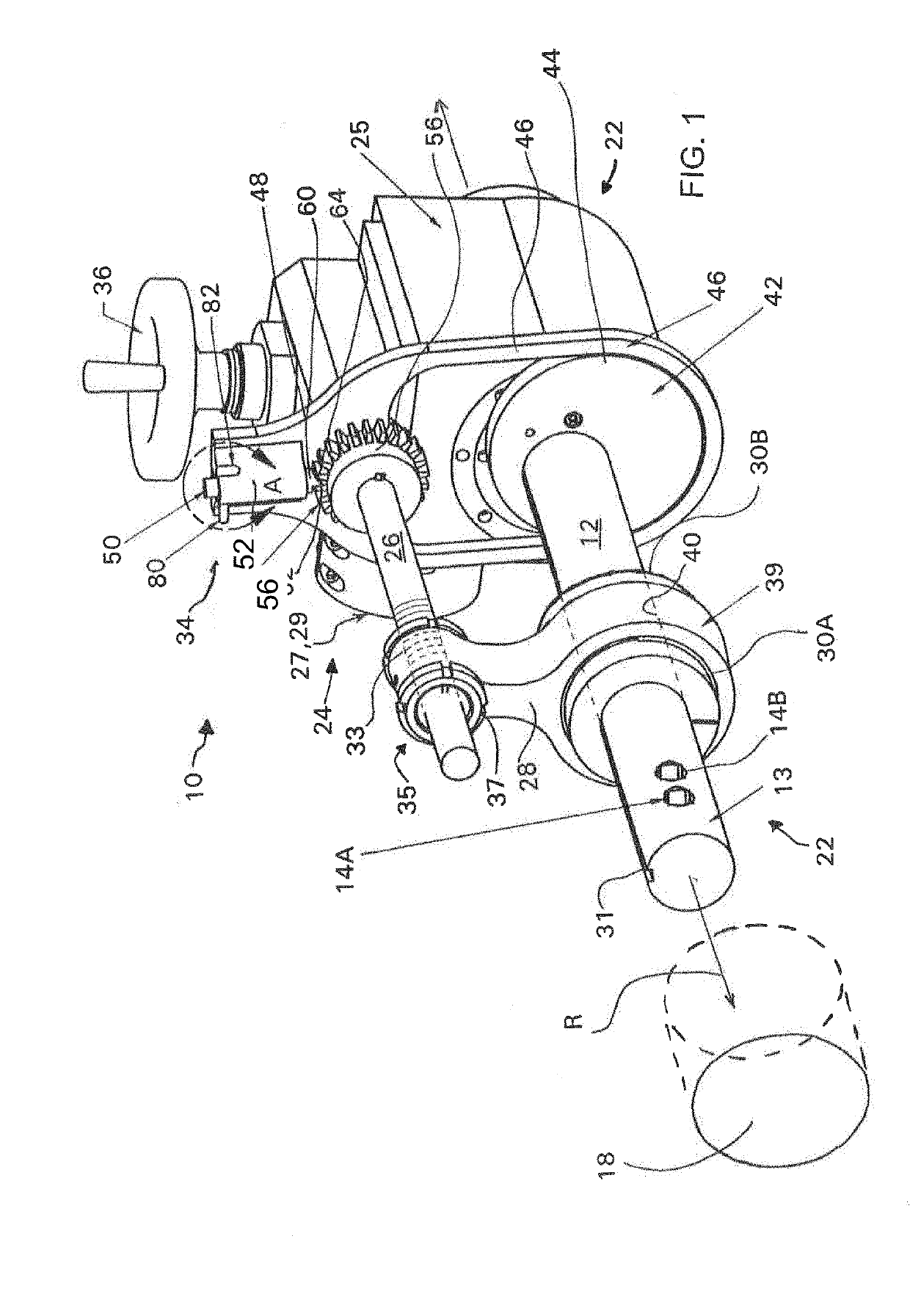
[0033]Turning now to FIG. 1, a diagrammatic representation of an exemplary boring bar mechanism 10, according to the present disclosure, is shown. As illustrated in FIG. 1, the boring bar mechanism 10 includes a rotatable and axially translatable cylindrical boring bar 12 typically having at least one and more commonly two spaced apart tool apertures or holders 14A, 14B located adjacent a working end 13 of the boring bar 12 for mounting various tools, such as a variety of cutting, milling, machining or finishing tools (not shown), for preforming a desired cutting, milling, machining or finishing operation within a bore 18 being repaired or ...


PUM


Abstract

A boring bar apparatus comprising a boring bar having at least one tool aperture formed therein. An axial translation mechanism for axially indexing the boring bar. The axial translation mechanism comprises a feed screw assembly having a threaded section, a rotational converter mechanism coupling the boring bar to the feed screw assembly for incrementally rotating the feed screw assembly, and a feed coupling having a first end engaging with the feed screw assembly and a second end engaging with the boring bar. The first end of the feed coupling having a threaded half nut section which, in a first position, engages with the feed screw assembly to facilitate axially indexing of the boring bar, and, in a second position, disengages from the feed screw assembly to facilitate moving both the feed coupling and the boring bar relative to the feed screw assembly to assist with repositioning of the boring bar.

Description

FIELD OF THE INVENTION[0001]The present invention relates to a number of improvement relating to various components of a boring bar apparatus.BACKGROUND OF THE INVENTION[0002]Heavy equipment and machinery frequently require repair and it is generally preferable that such repair be done in the field rather than transporting such machinery or equipment to a suitable repair facility, since this reduces the associated time and cost required for repair. One of the most commonly required repairs for large machinery or equipment is the repair or refurbishing of a bore, that is, a circular opening that supports an axle or a shaft, for example, as these circular openings eventually become damaged or worn due to a variety of reasons, including mechanical wear of the parts, thereby resulting in a need to restructure or reconstruct the bore to the proper diameter and shape. It may also be desirable to modify a bore for a number of reasons, such as reconstructing the bore to have a slightly larg...

Claims


Application Information

Patent Timeline
IPC IPC(8): B23B29/02
CPCB23B29/02
Inventor ESSLINGER, THOMAS
Owner BORE REPAIR SYST
Why Eureka
Try Eureka