Dual-color light emitting diode light strings

a diode light and diode technology, applied in the field of decorative light strings, can solve the problems of soldering joints cracking, soldering joints cracking, soldering material not as flexible, etc., and achieve good illumination effects

Active Publication Date: 2019-09-12
BLOOMING INT LTD
View PDF10 Cites 33 Cited by
  • Summary
  • Abstract
  • Description
  • Claims
  • Application Information

AI Technical Summary

Benefits of technology

[0016]In the present disclosure, the illumination devices are securely soldered between the first wire and the second wire, and provide good illumination effects. Moreover, embodiments of circuits of light strings in the present...

Problems solved by technology

When arranging a light string, which may include pulling the light string, the light sources may be subject to forces and shocks that result in solder joints cracking.
Furthermore, usually electric wires are flexible, but the soldering material is not as flexible.
Thus, when the electric wire of the light string is pulled ...

Method used


Image

  • Dual-color light emitting diode light strings
  • Dual-color light emitting diode light strings
  • Dual-color light emitting diode light strings

Examples


first embodiment

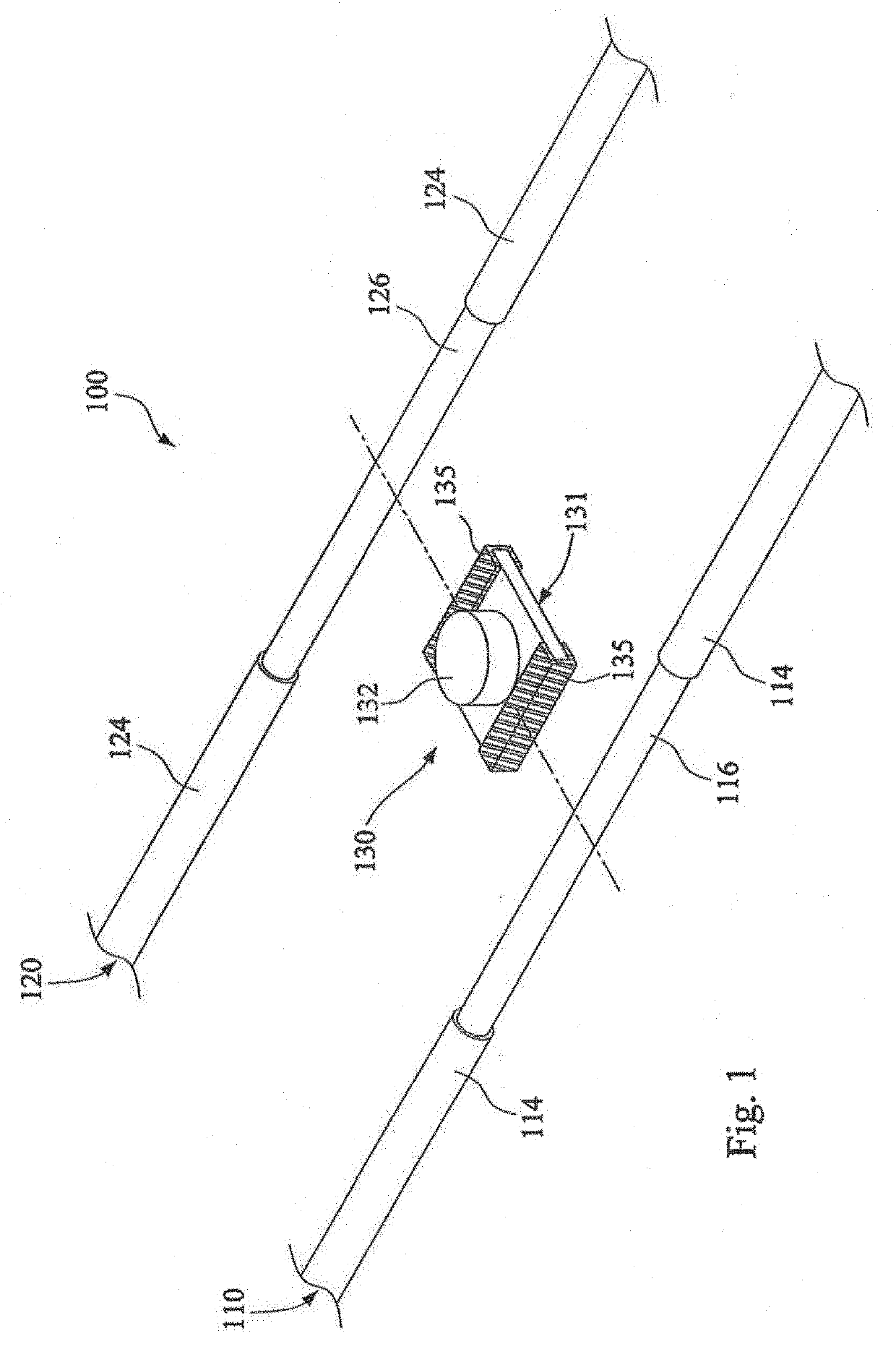
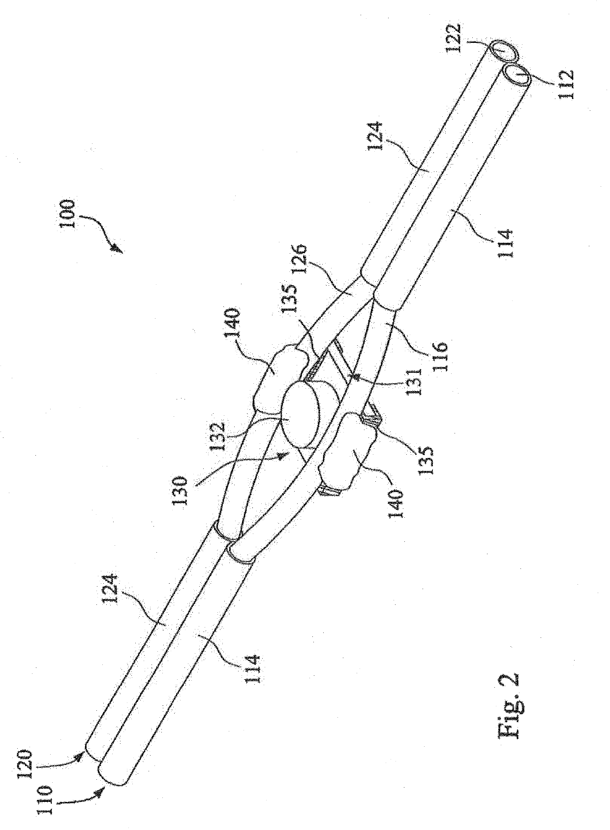
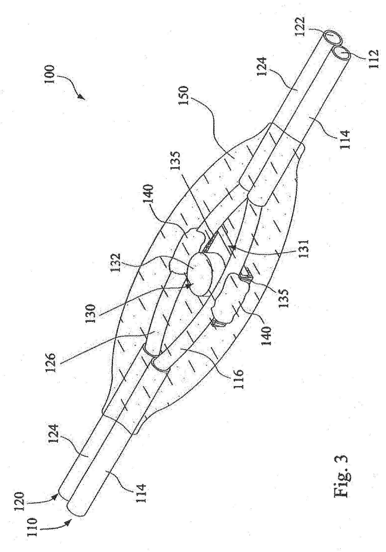
[0054]In an embodiment, the first conductor 112 and / or the second conductor 122 may be solid, single-strand conductors (single piece copper conductor or metal conductor made of an appropriate conductive metal, such as copper, a copper alloy, and so on) as is depicted in FIG. 1 to FIG. 5. Alternatively, the first conductor 112 and / or the second conducting wire 122 may comprise stranded conductors instead of a single piece conductor. In the first embodiment, the first second insulating layer 114 and the second insulating layer 124 are respectively plastic insulators, such as polyvinylchloride (PVC). In one or more embodiments, the first insulating layer114 and the second insulating layer 124 are very thin layers of insulation, such as an enamel coating, such that the first wire 110 or the second wire 120 are enameled wires. In one or more embodiments, the first insulating layer 114 and the second insulating layer 124 are combined into one piece for convenience of wire arrangement.

[005...

second embodiment

[0056]Referring to FIG. 6, a circuit 2 of the light string 100 is depicted according to the present disclosure. In the embodiment of FIG. 6, multiple illumination devices 130 are arranged in series and parallel on three wires to form light string 100.

[0057]As depicted in FIGS. 6, 6A and 6B, the circuit 2 in the second embodiment includes a first wire 110, a second wire 120, a third wire 160 and a plurality of illumination devices 130. Third wire 160 includes conductor 162 and insulation layer 164.

[0058]The first wire 110 is used to receive a first electric potential V1; and in one example, the first electric potential is 6V direct current (DC). The third wire 160 is used to receive a third electric potential V3; and in one example the third electric potential V3 is ground potential (GND). The second wire 120 is used as a connection node among the illumination devices 130.

[0059]In an embodiment, each of the illumination devices 130 is substantially identical to the illumination devic...

third embodiment

[0078]Similarly, in the third embodiment, the first wire 110, the second wire 120, the third wire 130 and the boost line 170 are arranged in parallel, the circuit 3 becomes a long single piece light string for convenience of wires arrangement.

[0079]Still referring to FIG. 8, in an embodiment, the circuit 3 further includes a current-limiting resistor 180, electrically connecting the first electric potential V1 to the first wire 110 for limiting current in the first wire 110. The current-limiting resistor 180 limits the current in the first wire 110, so as to prevent the illumination devices 130 from being damaged by over-current. Alternatively, the current-limiting resistor 180 is disposed on the boost line 170, which is also located on the serial current loop to limit the current thereon.


PUM


Abstract

A light string, comprising a first illumination device configured to emit a first color light; a second illumination device adjacent the first illumination device, and configured to emit a second color light, the second color being different from the first; a first wire including a first conductor and a first insulating layer, the first conductor partially exposed to form a first conductor soldering section; and a second wire, including a second conductor and a second insulating layer, the second conductor partially exposed to form a second conductor soldering section. The first conductor soldering section and the second conductor soldering section are attached to a pair of electrical contacts on each of the first and second illumination devices, and the first and second illumination devices are electrically biased such that either the first illumination device emits light or the second illumination device emits light, but not both at the same time.

Description

PRIORITY CLAIM[0001]The present application claims the benefit of U.S. Provisional Application No. 62 / 682,683, filed Jun. 8, 2018, and also claims priority to Chinese Patent Application No. 201810195592.5, filed Mar. 9, 2018, which are incorporated herein by reference in their entireties.FIELD OF THE INVENTION[0002]The instant disclosure relates to decorative light strings, and in particular, relates to light strings, circuits of light strings, and methods of manufacturing light strings.BACKGROUND OF THE INVENTION[0003]A light string that includes plural light sources directly soldered onto electric conductors at intervals, so as to form a string-shaped illumination device without a lamp holder, is known in the art. An example of such a light string is found in U.S. Pat. No. 8,397,381, entitled Method of Manufacturing Light Set with Surface Mounted Light Emitting Components. Light strings having many small-sized light sources, such as small bulbs that include light emitting diodes (...

Claims


Application Information

Patent Timeline
IPC IPC(8): F21S4/00F21V23/00F21V19/00
CPCF21V19/0025F21Y2113/13F21V23/003F21Y2115/10F21V23/001F21S4/00F21S4/26
Inventor SHAO, SHU FA
Owner BLOOMING INT LTD
Why Eureka
Try Eureka