Bidirectional wireless power transmission system

Active Publication Date: 2019-09-12
MURATA MFG CO LTD
View PDF0 Cites 3 Cited by
  • Summary
  • Abstract
  • Description
  • Claims
  • Application Information

AI Technical Summary

Benefits of technology

This patent allows for a more efficient and symmetrical power transfer between two circuits. This enables the control of the transmitted electric power through the driving frequency and duty ratio.

Problems solved by technology

In addition, in the one-way power transfer system, since a circuit network composed of a transmission transformer, a transmission electrode, a reception electrode, and a reception transformer is optimized for power transfer from the power transmission side to the power reception side and is asymmetrically designed, it is very difficult to provide power transfer in the reverse direction in principle.

Method used


Image

  • Bidirectional wireless power transmission system
  • Bidirectional wireless power transmission system
  • Bidirectional wireless power transmission system

Examples


second embodiment

[0085]The bidirectional wireless power transfer system adopting the electric field coupling method is described above in the first embodiment and the modifications of the first embodiment. However, it is noted that the exemplary embodiments of the present disclosure is applicable to a bidirectional wireless power transfer system adopting a magnetic field coupling method. The bidirectional wireless power transfer system adopting the magnetic field coupling method will now be described, focusing on the points different from the bidirectional wireless power transfer system adopting the electric field coupling method.

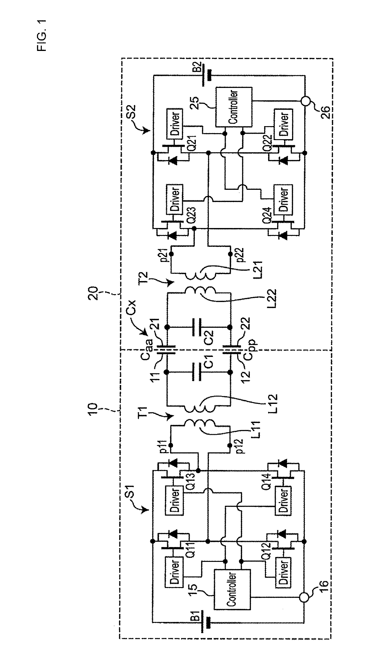
[0086]FIG. 6 is a circuit diagram of a bidirectional wireless power transfer system according to a second embodiment. The bidirectional wireless power transfer system includes the first power transfer apparatus 10 and the second power transfer apparatus 20.

[0087]Each of the first power transfer apparatus 10 and the second power transfer apparatus 20 is configured to operate...


PUM


Abstract

A first power transfer circuit in a first power transfer apparatus and a second power transfer circuit in a second power transfer apparatus are configured to be electrically symmetrical to each other. In transfer of electric power from one of the first and second power transfer apparatuses to the other of the first and second power transfer apparatuses, a controller drives a first switching circuit and a second switching circuit using a parallel resonant frequency of a complex resonant circuit as a reference frequency of an operating frequency. The controller changes the operating frequency to a frequency higher than the reference frequency or a frequency lower than the reference frequency if a duty ratio is maximized when transmitted electric power is lower than target electric power, which is a control target value, during the driving at the reference frequency.

Description

CROSS REFERENCE TO RELATED APPLICATIONS[0001]The present application is a continuation of PCT / JP2018 / 019865 filed May 23, 2018, which claims priority to Japanese Patent Application No. 2017-104824, filed May 26, 2017, the entire contents of each of which are incorporated herein by reference.TECHNICAL FIELD[0002]The present invention relates to a bidirectional wireless power transfer system that bidirectionally and wirelessly transmits electric power between a first power transfer apparatus and a second power transfer apparatus.BACKGROUND[0003]Patent Document 1 discloses a wireless power transfer system adopting an electric field coupling method.[0004]Patent Document 1: Japanese Patent No. 5741778.[0005]Although wireless power supply has hitherto been used in one-way power transfer from a power supply to a target, application of the wireless power supply to bidirectional power transfer, such as energy exchange between batteries, is expected in recent years.[0006]However, the wireless...

Claims


Application Information

Patent Timeline
IPC IPC(8): H02J50/12H02J7/02H02J50/05
CPCH02J50/12H02J50/05H02J7/025H02J7/342H02J7/00
Inventor KAWANAMI, YOSUKEICHIKAWA, KEIICHISUESADA, TSUYOSHI
Owner MURATA MFG CO LTD
Why Eureka
Try Eureka