Side view mirror assembly for a bicycle
- Summary
- Abstract
- Description
- Claims
- Application Information
AI Technical Summary
Benefits of technology
Problems solved by technology
Method used
Image

Examples
first embodiment
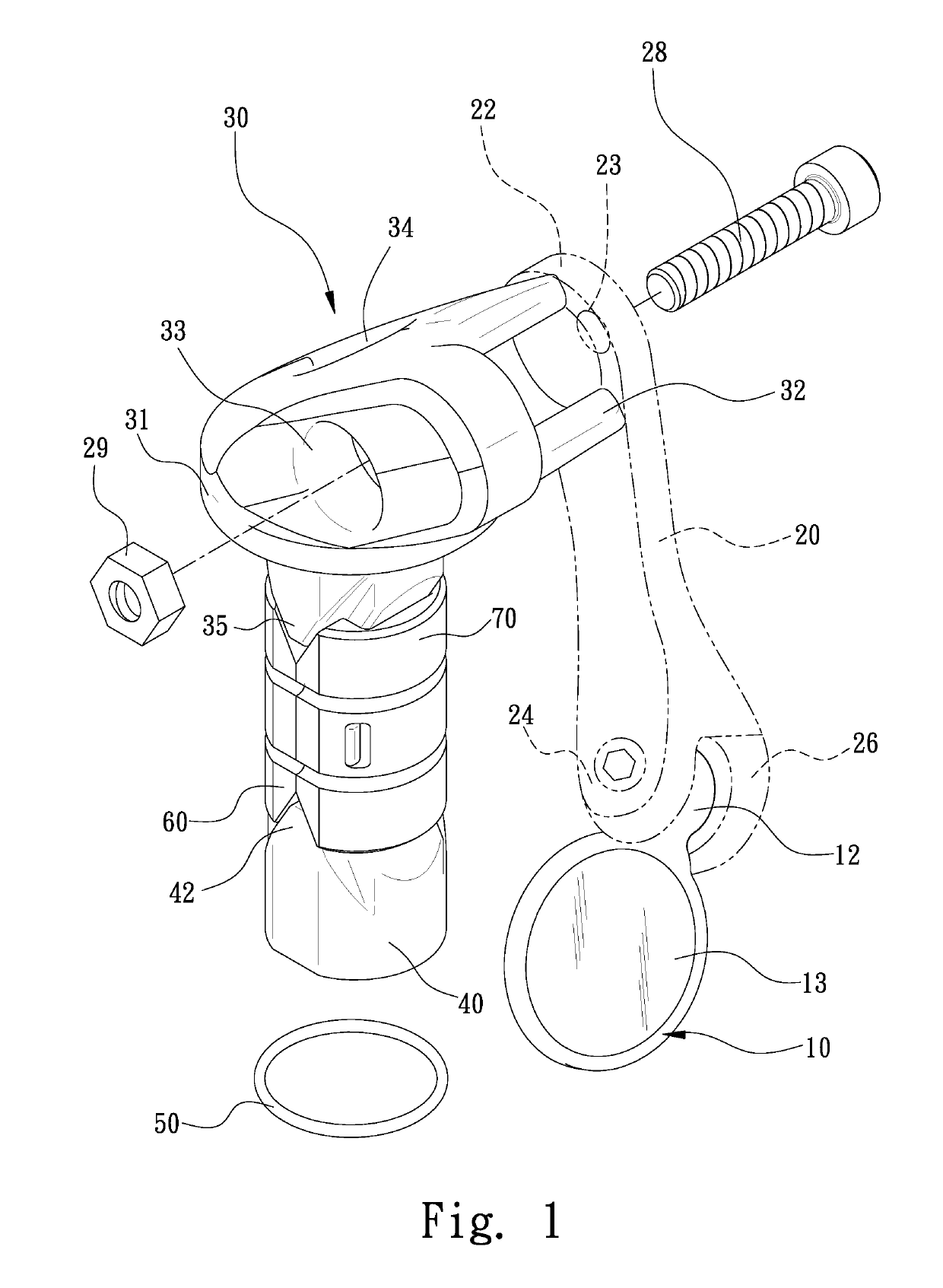
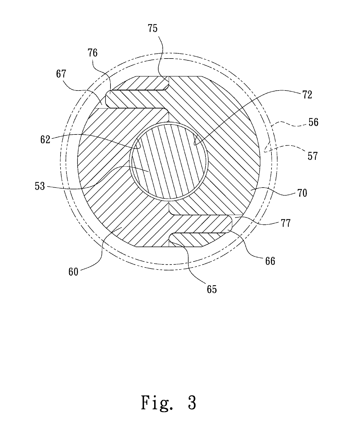
[0029]Referring to FIG. 1, a side view minor assembly includes a minor unit 10, a bar 20 and a plugging unit 30 according to the present invention. The minor unit 10 is connected to the plugging unit 30 via the bar 20. The side view minor assembly can be connected to a handle bar 56 (FIG. 3) by the plugging unit 30.
[0030]Referring to FIGS. 15 through 18, the side view minor unit 10 includes a frame 11, a minor 13 and a plate 15. The minor 13 is kept in the frame 11 by the plate 15.
[0031]The frame 11 includes a ring 14, a front annular flange 142 foimed along a front edge of the ring 14, a rear annular flange 144 foimed along a rear edge of the ring 14, an annular groove 141 made between the front annular flange 142 and the rear annular flange 144, and an opening 143 made in the front annular flange 142. The ring 14 extends in a circular manner in the first embodiment. The frame 11 further includes a ball 12 foimed on an external face of the ring 14. The frame 11 further includes a s...
second embodiment
[0037]Referring to FIGS. 17 and 18, there is a minor unit 10 according to the present invention. The second embodiment is identical to the first embodiment except for several features. Firstly, the frame 11 is made in a different shape. In specific, instead of the circular ring 14, a substantially elliptic ring 145 is used. Accordingly, the front annular flange 142 is made in a different shape. Secondly, the rear annular flange 144 is omitted. Thirdly, the arched fin 161 is omitted. Fourthly, the screw hole 18 is omitted. Fifthly, two countersink holes 162 are made in the front annular flange 142. Sixthly, two countersink holes 16 are made in the plate 15, and each of the countersink holes 16 includes a hexagonal larger portion. Seventhly, two threaded bolts 17 and two nuts 171 are used. Each of the nuts 171 is inserted in the hexagonal portion of a corresponding one of the countersink holes 16. Each of threaded bolts 17 is inserted through a corresponding one of the countersink hol...
PUM
 Abstract
Description
Claims
Application Information
 - Generate Ideas
- Intellectual Property
- Life Sciences
- Materials
- Tech Scout
- Unparalleled Data Quality
- Higher Quality Content
- 60% Fewer Hallucinations
Browse by: Latest US Patents, China's latest patents, Technical Efficacy Thesaurus, Application Domain, Technology Topic, Popular Technical Reports.
© 2025 PatSnap. All rights reserved.Legal|Privacy policy|Modern Slavery Act Transparency Statement|Sitemap|About US| Contact US: help@patsnap.com