Roof headwall and sloped wall flashing with ledge

a technology of roof headwall and sloped wall, applied in roofs, construction, buildings, etc., can solve the problems of wind pulling siding away from the wall, difficult to ensure the placement of siding or stucco, and difficulty in ensuring the stability of the roof, so as to effectively protect the building envelope from weather-related events

Active Publication Date: 2019-09-19
ROOFERS ADVANTAGE PRODCUTS LLC
View PDF24 Cites 0 Cited by
  • Summary
  • Abstract
  • Description
  • Claims
  • Application Information

AI Technical Summary

Benefits of technology

[0007]One object of the present invention is to provide a flashing system suitable for use on roof protrusions comprising both head and cheek walls that effectively protects the building envelope from weather-related events.
[0008]Another object of the present invention is to provide a flashing system that ensures consistent application of siding to the building envelope in the area surrounding roof protrusions comprising both head and cheek walls.
[0009]A flashing system headwall and sloped wall flashing components with ledges provides such benefits, as will be discussed further herein.

Problems solved by technology

Where siding or stucco is used on the wall, consistent placement of the siding or stucco is difficult.
This results in variability of siding reveals and also direct exposure of siding to weather events, which may be deflected by the roof and thereby drive rain underneath the siding and / or result in wind pulling the siding away from the wall.

Method used


Image

  • Roof headwall and sloped wall flashing with ledge
  • Roof headwall and sloped wall flashing with ledge
  • Roof headwall and sloped wall flashing with ledge

Examples


Embodiment Construction

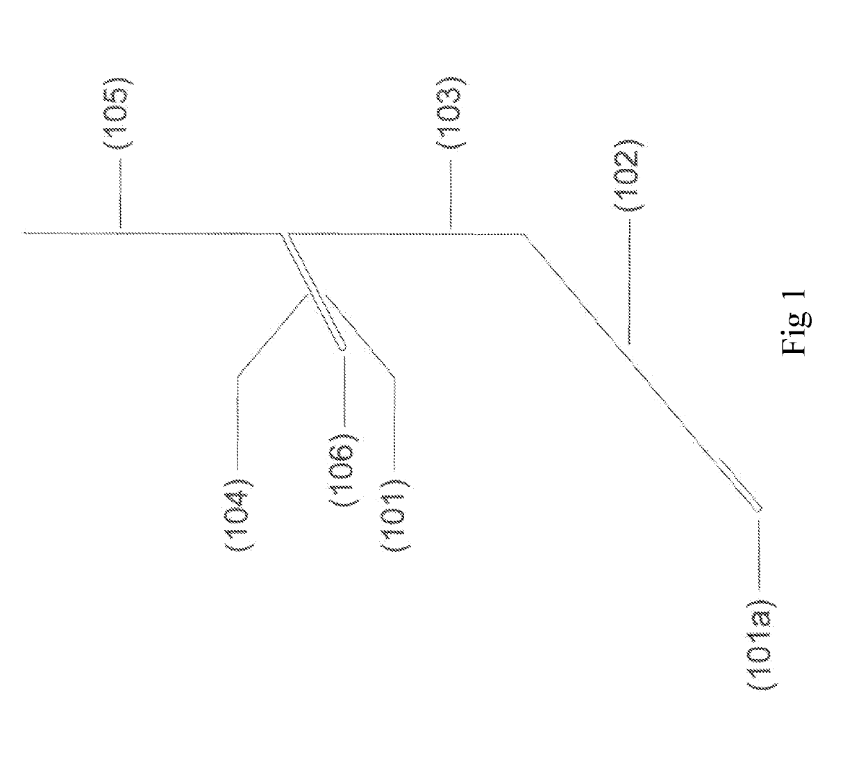
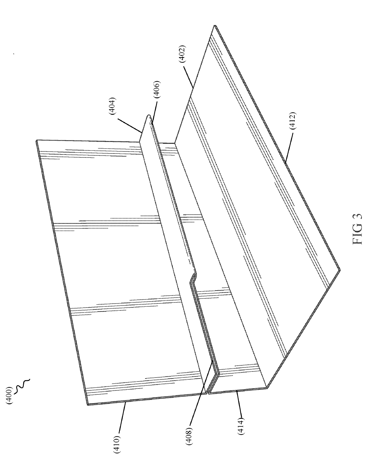
[0016]As the ledge of a sloped wall roof flashing terminates at a corner of a dormer or roof protrusion, a complimentary headwall flashing is required to ensure the building envelope is sufficiently protected. More specifically, the angle of the sloped ledge 400 of the sloped wall flashing 400 as it abuts a corner of a cheek wall 304 or similar location needs to be carried around to the front of the wall, i.e. the headwall side, where it can abut headwall flashing also having a ledge 104. If both ledge angles are not the same, relative to the roof slope, they will not interact seamlessly and be able to be joined in a watertight fashion.

[0017]Now referring to FIG. 1, headwall flashing with a ledge 104 designed to be used with sloped wall flashing 400, such as that shown in FIGS. 3 and 4, that is fabricated at an angle that corresponds to a roof slope to which it abuts at an outside corner location is shown.

[0018]More specifically, the headwall flashing with ledge 104, in embodiments,...


PUM


Abstract

Headwall flashing and sloped wall flashing, each having a ledge, where the ledges are designed to meet at an outside corner of a roof protrusion comprising a headwall and a cheek wall, the headwall flashing being configured to abut a face of the roof protrusion and having a downwardly-angled ledge that ties into the ledge of the sloped roof flashing, which is angled such that it forms a consistent ledge for installation of siding up a cheek wall, despite the siding creating a shimming effect that would typically result in a stepped appearance and misalignment thereof.

Description

RELATED APPLICATIONS[0001]This application claims the benefit of U.S. Provisional Application Nos. 65 / 662,365, filed Apr. 25, 2018, and No. 60 / 643,335, filed Mar. 15, 2018. Each of these applications is herein incorporated by reference in their entirety for all purposes.FIELD OF THE INVENTION[0002]The invention relates to roofing, and, more particularly, to flashing used in roof applications.BACKGROUND OF THE INVENTION[0003]A headwall is defined by the junction between a sloped roof and the face of a wall. It is typical to use metal flashing at this juncture to ensure that the building envelope is sealed against water intrusion. Such flashing is referred to as headwall flashing.[0004]Headwall flashing extends up the wall and is covered with exterior siding, stucco, or other finishes. A base of the headwall flashing typically extends over and onto the completed roofing system along the headwall, which may be contrasted with cheek walls, where each course of shingles is stepped out us...

Claims


Application Information

Patent Timeline
Patent Type & Authority Applications(United States)
IPC IPC(8): E04D13/147E04D1/30E04B7/18
CPCE04B7/18E04D1/30E04D2001/301E04D13/1475E04D2013/1422
Inventor FOLKERSEN, JONNY E.FOLKERSEN, BENJAMIN J.
Owner ROOFERS ADVANTAGE PRODCUTS LLC
Why Eureka
Try Eureka