Pressure regulating mass flow system for multipoint gaseous fuel injection

a gaseous fuel injection and pressure regulation technology, applied in mechanical equipment, electric control, machines/engines, etc., can solve the problems of low opening inability to determine the gas substitution percentage of dual fuel engines, and inability to adjust the gas intake valve size, so as to reduce the number of gas admission valve sizes, maximize the duration of gas admission valves, and improve turn down

Active Publication Date: 2019-09-19
WOODWARD GOVERNOR CO
View PDF23 Cites 0 Cited by
  • Summary
  • Abstract
  • Description
  • Claims
  • Application Information

AI Technical Summary

Benefits of technology

[0006]In particular, embodiments of the presently disclosed invention provide a gaseous fuel system and method having coordinated control between an engine controller, an electronic pressure regulator, and the gas admission valves. The controller is provided with certain physical parameters of the gaseous fuel system including system volume, gas admission valve duration, and engine fuel demand. In this way, both pressure and mass flow are able to be controlled independently through an electronic pressure regulation system. Accordingly, mechanical regulator pressure droop is eliminated by controlling pressure to the gas admission valves in a range that is optimized for their performance at a given fuel flow. Further, the fuel system experiences an improvement in turn down, potentially reducing the number of gas admission valve sizes required in the system. Further still, the system is able to operate at a minimum optimum pressurization so as to maximize the duration of the gas admission valves regardless of the load point. In this way, the accuracy and the repeatability of the system performance is enhanced.
[0007]A further advantage of the disclosed system and method relates to prevention of over-pressurization and under-pressurization of the fuel system downstream of the electronic pressure regulator through flow and pressure control. These pressurization conditions are created when a large differential pressure is created in the system, such as, for example, during the system's initial start-up filling transient, when a breaker trips causing the engine to go from full load to no load, or when the system is shut down and the shutoff valve is located far upstream of the fuel rail. Such events can create a pressure differential over the operational limit of the gas admission valves. The presently disclosed system and method avoid such pressurization events by using the electronic pressure regulator to provide a faster response to rail pressure during such events. Additionally, the electronic pressure regulator does not have to start in a normally open condition, which minimizes the likelihood of overpressurization.

Problems solved by technology

Further, the fixed pressure setting from the mechanical pressure regulator 110 can cause low opening durations for the gas admission valves 130 at low engine loads, which causes fuel flow inaccuracy.
Yet another potential disadvantage of this system configuration relates to the difficulty of determining the gas substitution percentage in dual fuel engines as a result of the gas admission valve 130 inaccuracy mentioned above.

Method used


Image

  • Pressure regulating mass flow system for multipoint gaseous fuel injection
  • Pressure regulating mass flow system for multipoint gaseous fuel injection
  • Pressure regulating mass flow system for multipoint gaseous fuel injection

Examples


Embodiment Construction

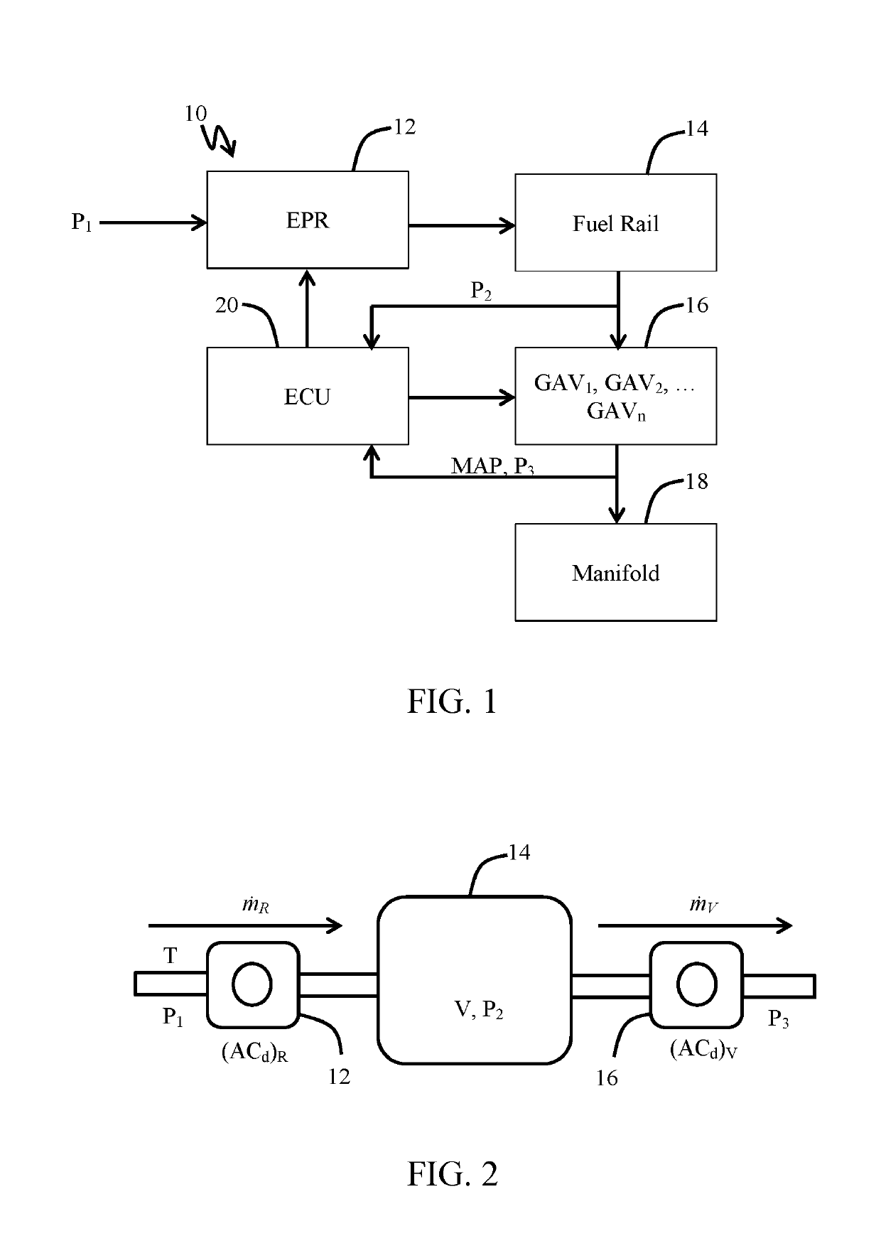
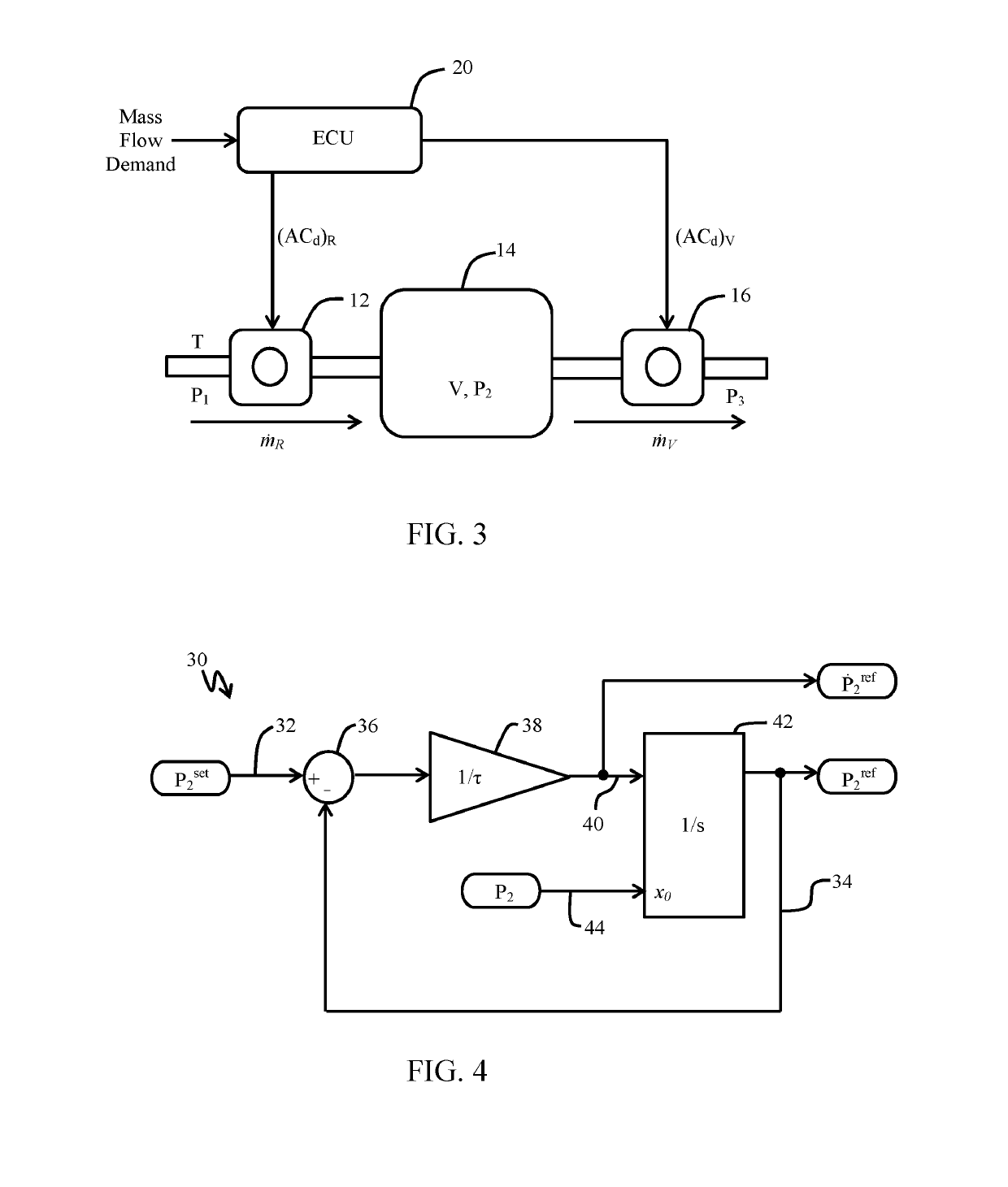
[0022]Embodiments of a gaseous or dual fuel electronic pressure regulation system (EPRS) for a multipoint fuel injection (MPFI) engine are described herein. Additionally, embodiments of a method for controlling the EPRS are provided. In particular, the EPRS employs an electronic pressure regulator (EPR) capable of accurately determining and controlling the mass flow of gaseous fuel into a fuel rail so as to avoid pressure droop and over- and under-pressurization of the gas admission valves (GAVs). In particular, using the disclosed EPRS provides another degree of freedom for controlling mass flow in a multipoint system. Conventional fuel control systems (such as those discussed above and shown in FIG. 8) have fixed supply pressures which can accentuate limitations of a MPFI system. By using the EPRS described above, mass flow is able to be controlled to the downstream manifold or engine cylinders very accurately, and the GAVs are able to be driven simultaneously in a pressure / pulse ...


PUM


Abstract

Embodiments of a gaseous or dual fuel electronic pressure regulation system (EPRS) for a multipoint fuel injection engine are described herein. Additionally, embodiments of a method for controlling the EPRS are provided. In particular, the EPRS employs an electronic pressure regulator (EPR) capable of accurately determining and controlling the mass flow of gaseous fuel into a fuel rail so as to avoid pressure droop and over- and under-pressurization of the gas admission valves (GAVs). By using the EPRS described above, mass flow is able to be distributed to the downstream manifold or engine cylinders very accurately, and the GAVs are able to be driven simultaneously in a pressure / pulse duration that is optimal for accurate and repeatable operation.

Description

FIELD OF THE INVENTION[0001]This invention generally relates to fuel systems and control systems for fuel systems. More particularly, this invention relates to fuel systems and method involving gaseous fuel.BACKGROUND OF THE INVENTION[0002]Conventionally, large reciprocating engines with multipoint fuel metering systems have a manifold absolute pressure (MAP) biased mechanical pressure regulator with a fixed pressure set point. That is, the mechanical pressure regulator is controlled based on feedback from MAP readings. FIG. 8 depicts such a conventional fuel system. As can be seen in relevant part, the gaseous fuel system 100 includes a mechanical pressure regulator 110 that controls the flow of a gaseous fuel into a fuel rail 120. The fuel rail 120 distributes the gaseous fuel to a plurality of gas admission valves 130. The gas admission valves 130 are controlled by a controller 140 that receives a mass flow demand and sets the duration of the opening and closing of the gas admiss...

Claims


Application Information

Patent Timeline
Patent Type & Authority Applications(United States)
IPC IPC(8): F02D19/02F02D41/40F02D41/38F02M21/02
CPCF02M21/0239F02D41/3854F02D19/023F02D19/022F02D19/027F02D41/402F02D19/0605F02D41/0027F02D41/3845F02D2200/0602F02M21/0245Y02T10/30
Inventor FARROW, TIMOTHY J.BUEHNER, MICHAEL RYANHAMPSON, GREGORY JAMESKARSPECK, JOHN
Owner WOODWARD GOVERNOR CO
Why Eureka
Try Eureka