Capacitive electromagnetic flowmeter

a flowmeter and capacitive technology, applied in the field of capacitive electromagnetic flowmeters, can solve the problems of low accuracy, low accuracy, and low accuracy of measurement accuracy of electromagnetic flowmeters, and achieve the effect of reducing temperature drift and high accuracy

Active Publication Date: 2019-09-19
YAMATAKE HONEYWELL CO LTD
View PDF0 Cites 3 Cited by
  • Summary
  • Abstract
  • Description
  • Claims
  • Application Information

AI Technical Summary

Benefits of technology

[0028]The present disclosure provides a capacitive electromagnetic flowmeter that can reduce, without requiring guard electrodes or shielded cables, the thermal effect from the exciting coil or fluid and the effect of magnetic flux differential noise caused by the magnetic circuit. This makes it possible to reduce temperature drift in the preamplifier caused by the thermal effect and thus to measure the flow rate with high accuracy.

Problems solved by technology

Capacitive electromagnetic flowmeters have been a particular focus of attention in recent years, because electrodes do not easily deteriorate and have low maintenance requirements.
This leads to extremely high impedance between the fluid and the electrodes, and makes a first-stage signal amplifying circuit susceptible to noise.
If noise is superimposed on lines between the electrodes and the input terminal of the signal amplifying circuit, the measurement accuracy and stability of the electromagnetic flowmeter may be degraded.
The capacitive electromagnetic flowmeter based on Related Technique 1 is disadvantageous in that wiring materials are costly and the wiring is complex.
The capacitive electromagnetic flowmeter based on Related Technique 2 is disadvantageous in that it is susceptible not only to heat from the exciting coils and the fluid, but also to magnetic flux differential noise from the magnetic circuit.
This is disadvantageous, as described above, in that the wiring materials are costly and the wiring is complex.
The thermal effect causes the occurrence of different temperature drifts in the preamplifiers 95A and 95B, and deteriorates measurement accuracy.
Therefore, the exciting frequency cannot be increased, and this leads to increased susceptibility to 1 / f noise.
To reduce the magnetic flux differential noise, it is necessary to minimize a loop area S of the signal loop LP as viewed in the magnetic flux direction Y. However, the longer the shielded lines 94A and 94B, the more difficult it is to reduce the loop area S.

Method used


Image

  • Capacitive electromagnetic flowmeter
  • Capacitive electromagnetic flowmeter
  • Capacitive electromagnetic flowmeter

Examples


first embodiment

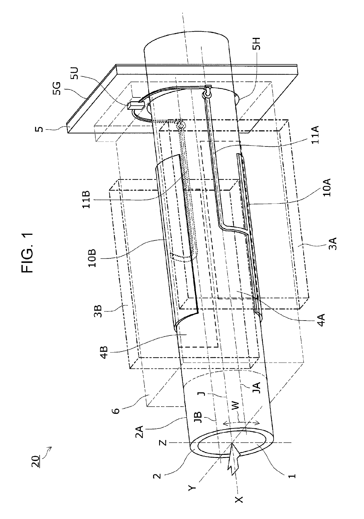
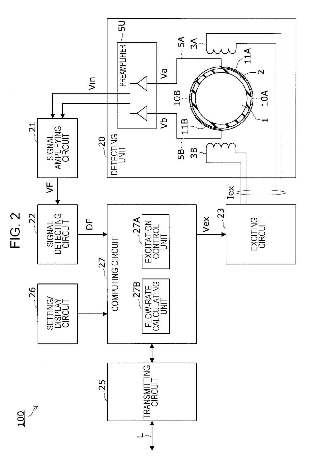
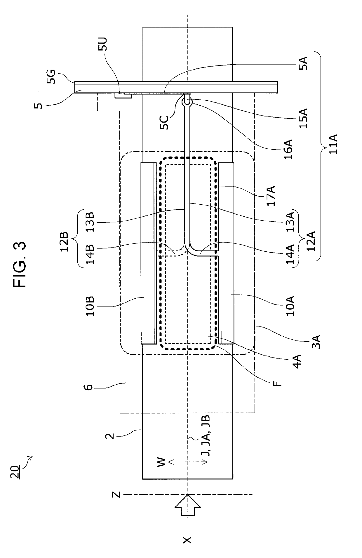
[0048]First, with reference to FIGS. 1 and 2, a capacitive electromagnetic flowmeter 100 according to a first embodiment of the present disclosure will be described. FIG. 1 is a perspective view illustrating a detecting unit of a capacitive electromagnetic flowmeter according to the first embodiment. FIG. 2 is a block diagram illustrating a circuit configuration of the capacitive electromagnetic flowmeter according to the first embodiment.

(Capacitive Electromagnetic Flowmeter)

[0049]In the capacitive electromagnetic flowmeter 100, a magnetic flux applied by an exciting coil produces electromotive force in a fluid (object to be measured) flowing in a measuring tube, and electrodes on the outer periphery of the measuring tube detect the electromotive force using capacitance between the fluid and the electrodes. The detected electromotive force is then amplified, sampled, and subjected to signal processing. With this configuration, the capacitive electromagnetic flowmeter 100 measures t...

second embodiment

[0100]A capacitive electromagnetic flowmeter according to a second embodiment of the present disclosure will now be described with reference to FIG. 7. FIG. 7 is a front view of a detecting unit according to the second embodiment.

[0101]In the first embodiment, the preamplifier substrate 5 is attached to the measuring tube 2 by securing the edge of the tube hole 5H, with an adhesive, to the outer periphery 2A of the measuring tube 2 passing through the tube hole 5H. In the present embodiment, the preamplifier substrate 5 is attached to the measuring tube 2 by pressing the edge of the tube hole 5H into contact with the outer periphery 2A of the measuring tube 2.

[0102]As illustrated in FIG. 7, the preamplifier substrate 5 of the present embodiment has a plurality of protrusions 5T along the perimeter of the tube hole 5H and allows the protrusions 5T to abut against the outer periphery 2A. This means that the edge of the tube hole 5H only partially comes into contact with the outer peri...

third embodiment

[0105]The detecting unit 20 of the capacitive electromagnetic flowmeter 100 according to a third embodiment of the present disclosure will now be described with reference to FIGS. 8 to 10. FIG. 8 is a top view of a detecting unit according to the third embodiment. FIG. 9 is a side view of the detecting unit according to the third embodiment. FIG. 10 is a front view of the detecting unit according to the third embodiment.

[0106]In the first embodiment described above, the surface electrodes 10A and 10B, the connection lines 11A and 11B, and the preamplifier 5U are shielded together by one shielding case 6. In the present embodiment, however, the preamplifier 5U is shielded independently of the surface electrodes 10A and 10B and the connection lines 11A and 11B.

[0107]As illustrated in FIGS. 8 to 10, the detecting unit 20 according to the present embodiment includes two shielding cases 6A and 6B, and is configured such that the surface electrodes 10A and 10B and the connection lines 11A...


PUM


Abstract

A preamplifier substrate on which a preamplifier is mounted, the preamplifier being configured to amplify electromotive forces detected by a pair of surface electrodes, is disposed outside a flux region where a magnetic flux is produced, and the preamplifier substrate extends in a direction intersecting a measuring tube.

Description

CROSS-REFERENCE TO RELATED APPLICATIONS[0001]The present application is based on and claims priority to Japanese Application No. 2018-045387, filed Mar. 13, 2018, the entire contents of which are incorporated herein by reference.BACKGROUND1. Field[0002]The present disclosure relates to a capacitive electromagnetic flowmeter that measures the flow rate of a fluid without requiring electrodes for detecting electromotive force generated in the fluid to come into contact with the fluid.2. Description of the Related Art[0003]An electromagnetic flowmeter is a measuring instrument that includes an exciting coil configured to generate a magnetic field in a direction orthogonal to the longitudinal direction of the flow of a fluid in a measuring tube, and a pair of electrodes disposed on the measuring tube so as to extend in a direction orthogonal to the magnetic field generated by the exciting coil. The electromagnetic flowmeter detects electromotive force generated between the electrodes wh...

Claims


Application Information

Patent Timeline
Patent Type & Authority Applications(United States)
IPC IPC(8): G01F1/60G01F1/58
CPCG01F1/60G01F1/588G01F1/584G01F1/58G01F1/586
Inventor MOMOSE, OSAMUINAGAKI, HIROYUKIMAMADA, KOUICHIYAMAZAKI, YOSHIOYAMASHITA, TAKUMI
Owner YAMATAKE HONEYWELL CO LTD
Why Eureka
Try Eureka