Vehicle control device

a technology for controlling devices and vehicles, applied in vehicle position/course/altitude control, process and machine control, instruments, etc., can solve the problems of increased psychological burden and physical burden, difficulty in vehicle control, etc., and achieve the effect of reducing the burden of driving on the vehicle occupants

Inactive Publication Date: 2019-09-19
HONDA MOTOR CO LTD
View PDF0 Cites 4 Cited by
  • Summary
  • Abstract
  • Description
  • Claims
  • Application Information

AI Technical Summary

Benefits of technology

[0025]In the above configuration, the host vehicle travels along the travel trajectory of the preceding vehicle. Thus, the host vehicle can travel in the construction section relatively easily.
[0026]By the present invention, the burden of driving on the vehicle occupant can be reduced.

Problems solved by technology

For example, in a road where construction is performed as disclosed in Japanese Laid-Open Patent Publication No. 2009-156783, it may be difficult to perform the vehicle control compared with a case in a normal road because of bad condition of a road surface or the like.
Therefore, a psychological burden and a physical burden increase in traveling.

Method used


Image

  • Vehicle control device
  • Vehicle control device
  • Vehicle control device

Examples


embodiment 1

[4.1 Embodiment 1]

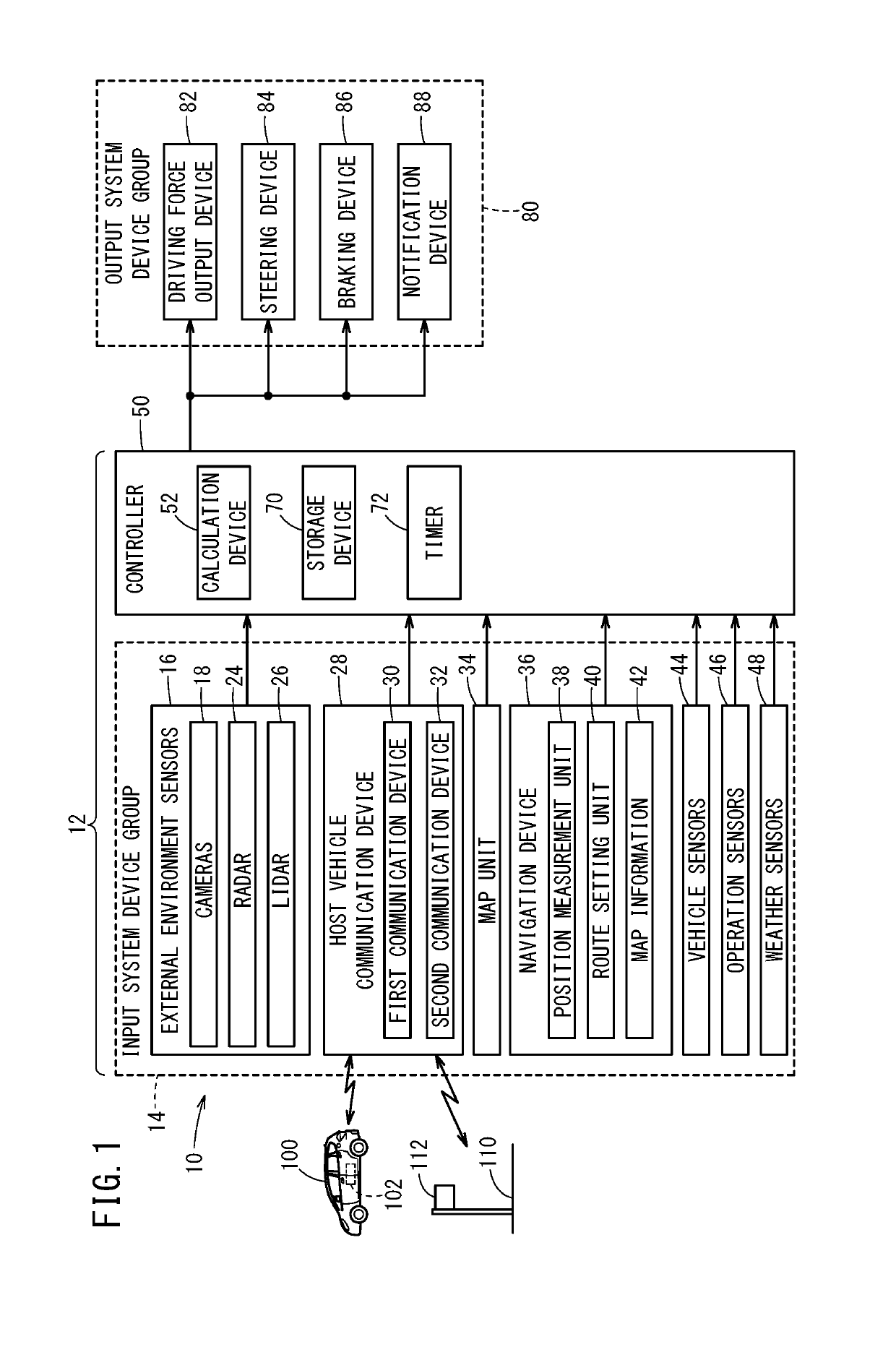
[0058]An operation of the vehicle control device 12 according to Embodiment 1 is described with reference to FIG. 4. A process shown in FIG. 4 is performed at predetermined time intervals while the vehicle control device 12 performs the automated driving.

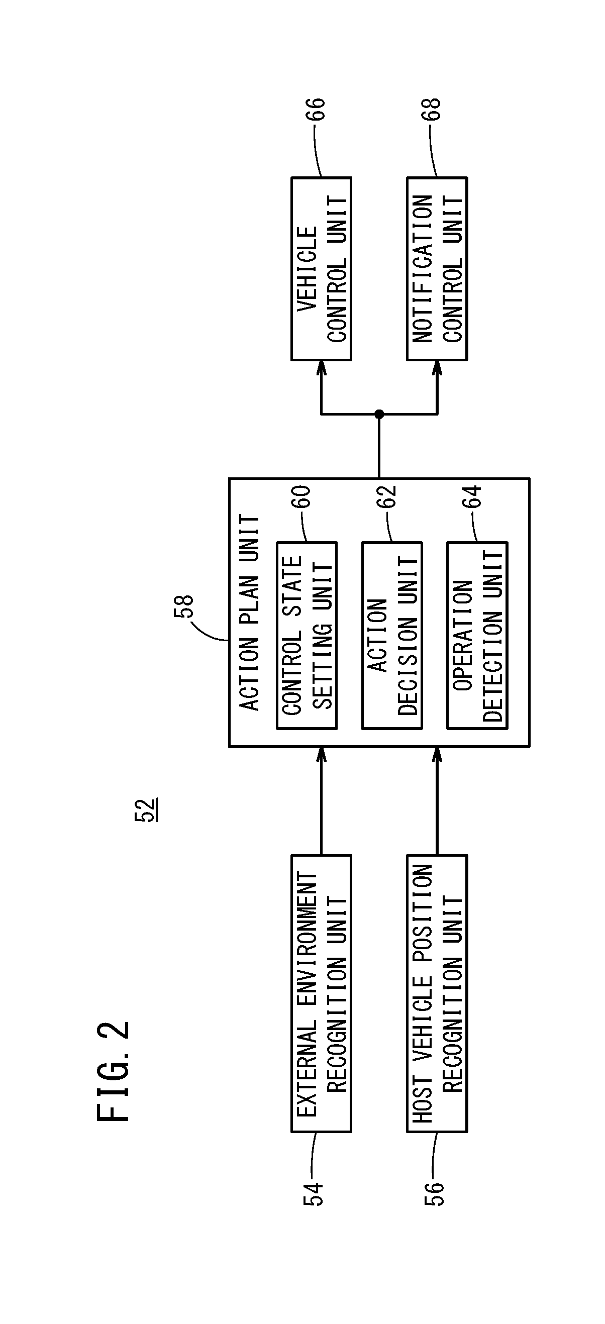
[0059]In step S1, the external environment recognition unit 54 recognizes the peripheral state of the host vehicle 10 on the basis of the latest information that is output from the input system device group 14. Note that the external environment recognition unit 54 recognizes the peripheral state of the host vehicle 10 periodically in parallel with each process below.

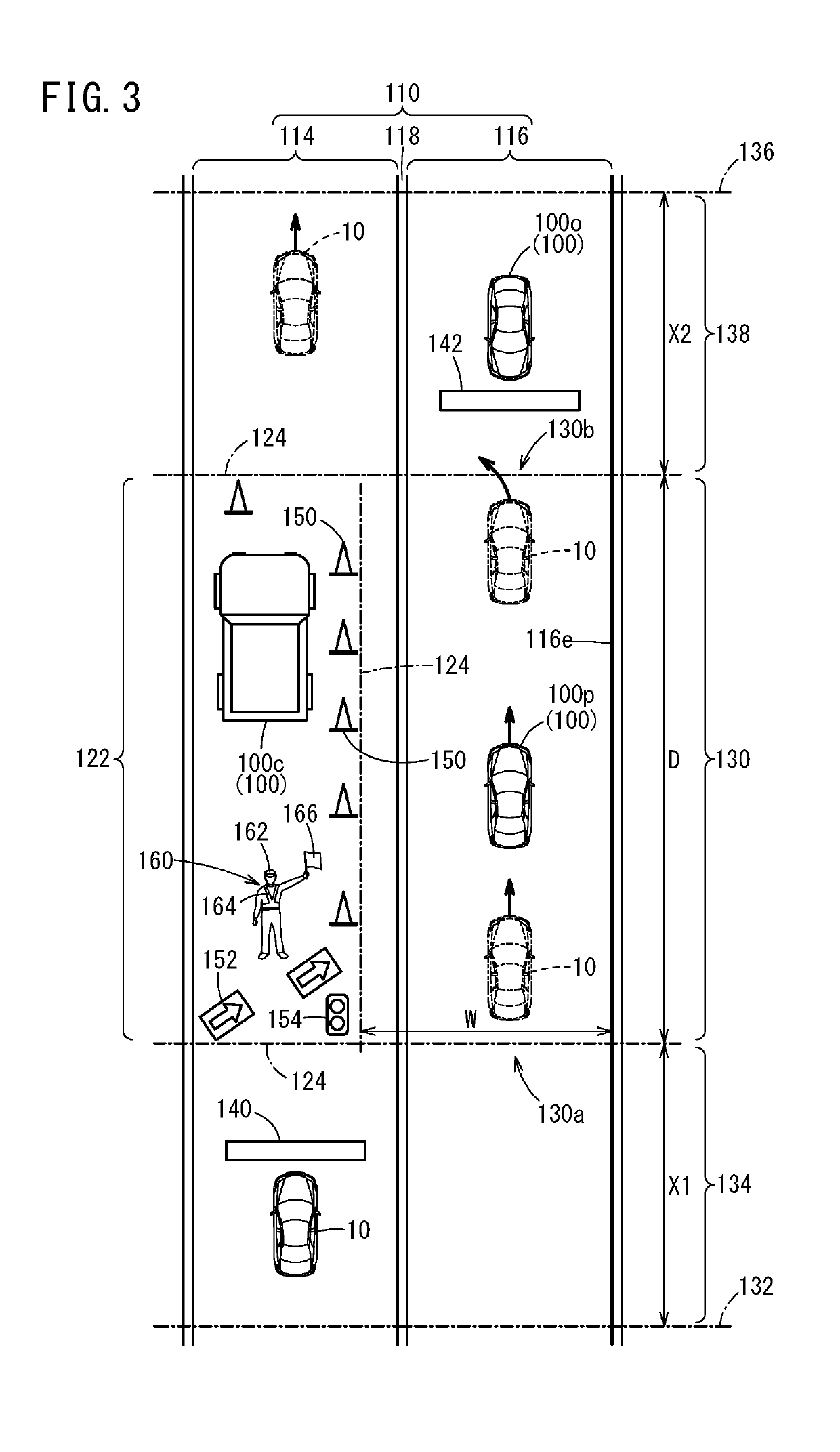
[0060]In step S2, the external environment recognition unit 54 recognizes whether the construction section 130 exists. For example, it is recognized whether the construction section 130 exists by identifying the installation object peculiar to the construction site 122 (the cones 150, the sign 152, the temporary traffic light 154, or the like), the con...

embodiment 2

[4.2 Embodiment 2]

[0071]An operation of the vehicle control device 12 according to Embodiment 2 is described with reference to FIG. 6. In Embodiment 1, the automated driving level is set based on the travel environment information recognized by the external environment recognition unit 54. On the other hand, in Embodiment 2, a predetermined automated driving level is set when the external environment recognition unit54 recognizes the construction section 130. A process shown in FIG. 6 is performed at predetermined time intervals while the vehicle control device 12 performs the automated driving.

[0072]Processes of step S11, step S12, step S14, and step S15 in FIG. 6 correspond to the processes of step S1, step S2, step S5, and step S6 in FIG. 4. Thus, description of these processes is omitted.

[0073]When the process has advanced from step S12 to step S13, the control state setting unit 60 sets the automated driving level. Here, the automated driving level is set to a predetermined aut...

embodiment 3

[4.3 Embodiment 3]

[0074]As shown in FIG. 7, Embodiment 1 and Embodiment 2 may be combined. Processes of step S21, step S22, and step S24 to step S27 among processes in FIG. 7 correspond to the processes of step S1 to step S6 in FIG. 4. In addition, a process of step S23 among the processes in FIG. 7 corresponds to the process of step S13 in FIG. 6.

[5. Examples of Additional Control]

[0075]In step S5 in FIG. 4, various kinds of control that can be performed in the automated driving level that is set at that time may be further performed. Examples of the various kinds of control are described below.


PUM


Abstract

An external environment recognition unit recognizes a peripheral state of a host vehicle. A control state setting unit sets a control state of automated driving. An action decision unit decides an action of the host vehicle on the basis of the peripheral state that is recognized by the external environment recognition unit and the control state that is set by the control state setting unit. If the external environment recognition unit recognizes a construction section in a road, the control state setting unit sets the control state in accordance with the construction section. A vehicle control unit performs travel control of the host vehicle on the basis of a decision result from the action decision unit.

Description

CROSS-REFERENCE TO RELATED APPLICATION[0001]This application is based upon and claims the benefit of priority from Japanese Patent Application No. 2018-046218 filed on Mar. 14, 2018, the contents of which are incorporated herein by reference.BACKGROUND OF THE INVENTIONField of the Invention[0002]The present invention relates to a vehicle control device that performs automated driving or driving assistance of a host vehicle.Description of the Related Art[0003]Japanese Laid-Open Patent Publication No. 2009-156783 discloses a navigation device that includes a host vehicle position recognition device. This navigation device corrects host vehicle position information expressing the current position of the host vehicle on the basis of a result of recognizing a ground object or the like. On the other hand, the navigation device does not correct the host vehicle position information when the ground object is moved by construction work, for example. Thus, the navigation device can recognize ...

Claims


Application Information

Patent Timeline
Patent Type & Authority Applications(United States)
IPC IPC(8): G05D1/00G05D1/02B60W50/14
CPCB60W2300/17G05D1/0257G05D2201/0202G05D1/0088B60W50/14G05D1/021G05D1/0061G05D1/0223G05D1/0246G05D2201/0212B60W30/182B60W60/0015B60W2552/00B60W2554/00B60W2555/20
Inventor MIURA, HIROSHIYANAGIHARA, SUGURUTAKADA, YUTAKOBAYASHI, SHOGO
Owner HONDA MOTOR CO LTD
Why Eureka
Try Eureka