Fuel cell stack, fuel cell stack dummy cell, method of producing dummy cell

a technology of fuel cell stack and dummy cell, which is applied in the direction of fuel cells, solid electrolyte fuel cells, collectors/separators, etc., can solve the problems of not being able to achieve the desired power generation stability of the fuel cell stack, the fuel gas and the oxygen-containing gas (reactant gases) are not diffused smoothly, and the power generation is not performed. achieve the effect of improving the power generation stability

Active Publication Date: 2019-09-19
HONDA MOTOR CO LTD
View PDF2 Cites 2 Cited by
  • Summary
  • Abstract
  • Description
  • Claims
  • Application Information

AI Technical Summary

Benefits of technology

[0007]A main object of the present invention is to provide a fuel cell stack which makes it possible to improve the power generation stability.

Problems solved by technology

When the temperature of the end sides of the stack body becomes low due to influence of the external temperature, etc., and water condensation occurs, there is a concern that the fuel gas and the oxygen-containing gas (reactant gases) are not diffused smoothly, and the desired power generation stability of the fuel cell stack may not be achieved.
In the dummy cells, since metal plates are used instead of electrolyte membranes, power generation is not performed, and water is not produced.

Method used


Image

  • Fuel cell stack, fuel cell stack dummy cell, method of producing dummy cell
  • Fuel cell stack, fuel cell stack dummy cell, method of producing dummy cell
  • Fuel cell stack, fuel cell stack dummy cell, method of producing dummy cell

Examples


Embodiment Construction

[0069]A preferred embodiment of a method of producing a fuel cell stack, a fuel cell stack dummy cell, a dummy cell according to the present invention will be described in detail with reference to the accompanying drawings. In the drawings, the constituent elements which have the same or similar functions and which offer the same or similar advantages are labeled with the same reference numerals, and description of such constituent elements will be omitted as necessary.

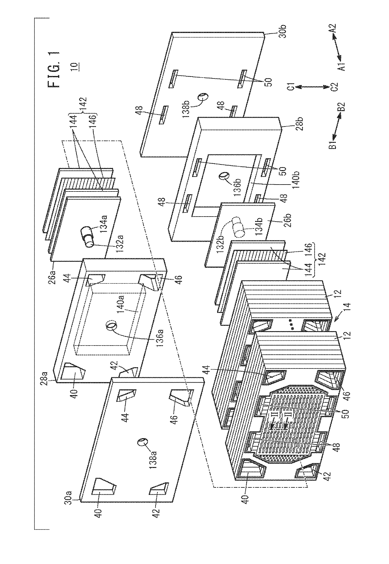
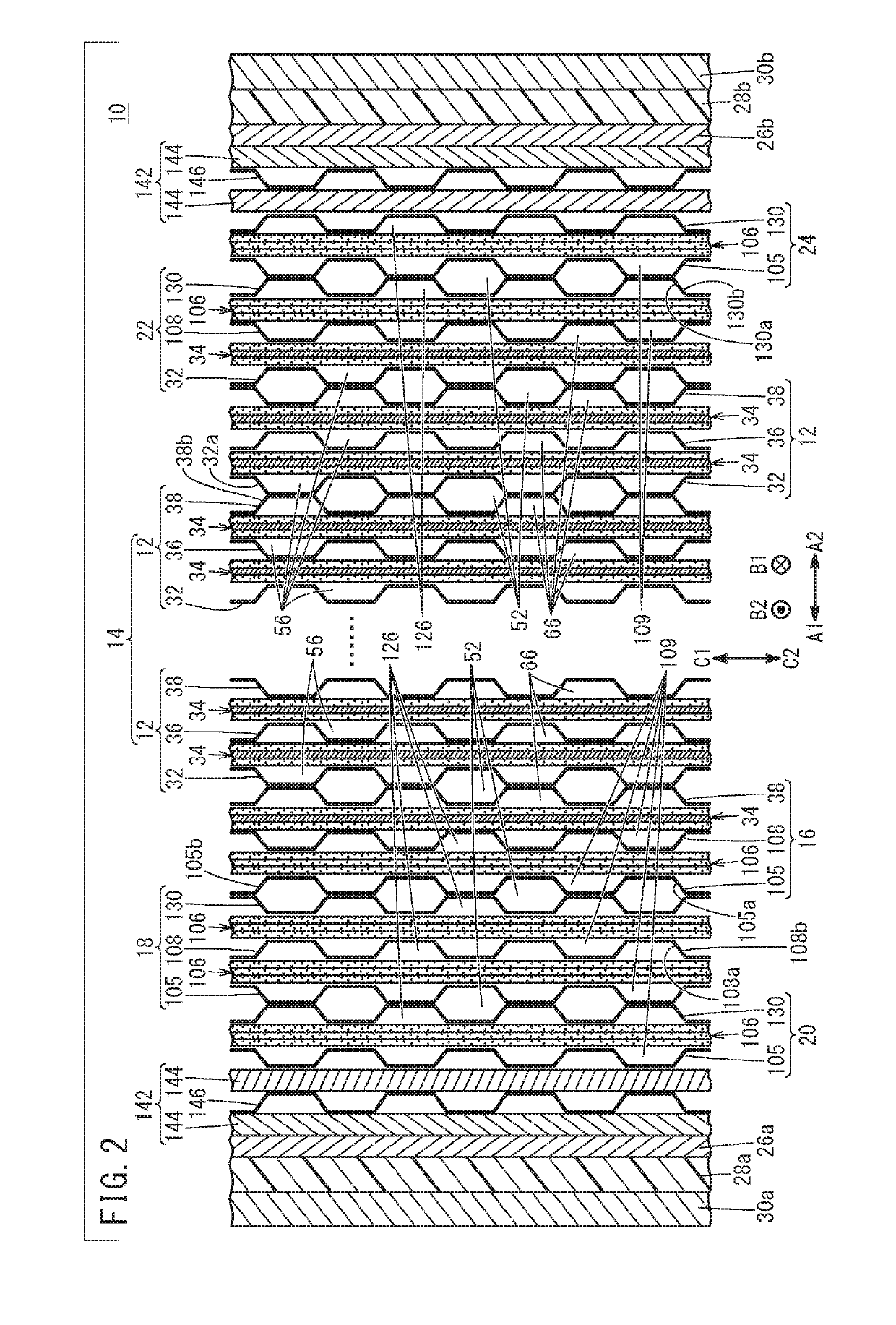
[0070]As shown in FIGS. 1 and 2, the fuel cell stack 10 according to an embodiment of the present invention includes a stack body 14 formed by stacking a plurality of power generation cells 12 in a horizontal direction (indicated by arrows A1 and A2) or in the gravity direction (indicated by arrows C1 and C2). For example, the fuel cell stack 10 is mounted in a fuel cell vehicle such as a fuel cell electric automobile (not shown).

[0071]As shown in FIG. 2, at one end of the stack body 14 in a stacking direction of the ...


PUM

PropertyMeasurementUnit
electrically conductiveaaaaaaaaaa
surface sizeaaaaaaaaaa
structureaaaaaaaaaa

Abstract

A fuel cell stack at least includes a stack body formed by stacking a plurality of power generation cells in a stacking direction and a first dummy cell provided at one end of the stack body in the stacking direction. The power generation cell includes a membrane electrode assembly. The first dummy cell includes a dummy assembly formed by stacking together three electrically conductive porous bodies each having a different surface size, a dummy resin frame member formed around the dummy assembly, and dummy separators.

Description

CROSS-REFERENCE TO RELATED APPLICATIONS[0001]This application is based upon and claims the benefit of priority from Japanese Patent Applications No. 2018-047748 filed on Mar. 15, 2018, No. 2018-047532 filed on Mar. 15, 2018, No. 2018-096340 filed on May 18, 2018, and No. 2018-110182 filed on Jun. 8, 2018, the contents all of which are incorporated herein by reference.BACKGROUND OF THE INVENTIONField of the Invention[0002]The present invention relates to a fuel cell stack including a stack body and a dummy cell. The stack body is formed by stacking a plurality of power generation cells together in a stacking direction. Each of the power generation cells includes a membrane electrode assembly, a resin frame member provided around the membrane electrode assembly, and separators. The dummy cell is provided at least at one end of the stack body in the stacking direction. Further, the present invention relates to a fuel cell stack dummy cell, and a method of producing the dummy cell.Descr...

Claims


Application Information

Patent Timeline
Patent Type & Authority Applications(United States)
IPC IPC(8): H01M8/0263H01M8/023H01M8/12H01M8/241H01M8/2457H01M8/0271
CPCH01M8/12H01M8/241H01M8/2457H01M8/023H01M8/0263H01M8/0271H01M2008/1095H01M8/2465H01M8/0297H01M8/1004H01M8/2404H01M8/04067Y02E60/50
Inventor INOUE, DAISUKEAOKI, SATOSHITANAKA, YUKIHITO
Owner HONDA MOTOR CO LTD
Why Eureka
Try Eureka