
Railway truck fault diagnosis system on basis of power sharing

A fault diagnosis system and power sharing technology, which is applied in the direction of measuring electricity, measuring electrical variables, and testing electrical devices in transportation, etc., which can solve the problems of unstable power generation of fault diagnosis devices, affecting work effects, and unbalanced voltages of sensors or hosts.

Active Publication Date: 2019-04-19
TANGZHI SCI & TECH HUNAN DEV CO LTD
View PDF8 Cites 0 Cited by
  • Summary
  • Abstract
  • Description
  • Claims
  • Application Information

AI Technical Summary

Problems solved by technology

However, since the carriages of railway freight cars are not electrified except for the live head, the fault diagnosis device installed in the carriage cannot work by connecting the power supply of the carriage, so a fault diagnosis device is needed to solve the problem of self-power supply
[0003] However, the sensors or hosts that can generate electricity in the current fault diagnosis device only supply power for themselves. In some cases, when external factors affect the generated voltage, it will cause voltage imbalance between different sensors or hosts. For example, when the vehicle is in the When the station is parked, it cannot generate electricity. When the vehicle is running at low speed, the generated voltage is less, and when it is running at high speed, the generated voltage is sufficient, so that the entire fault diagnosis device is in an unstable state of power generation, which affects its working effect.

Method used


Image

  • Railway truck fault diagnosis system on basis of power sharing
  • Railway truck fault diagnosis system on basis of power sharing
  • Railway truck fault diagnosis system on basis of power sharing

Examples


Embodiment Construction

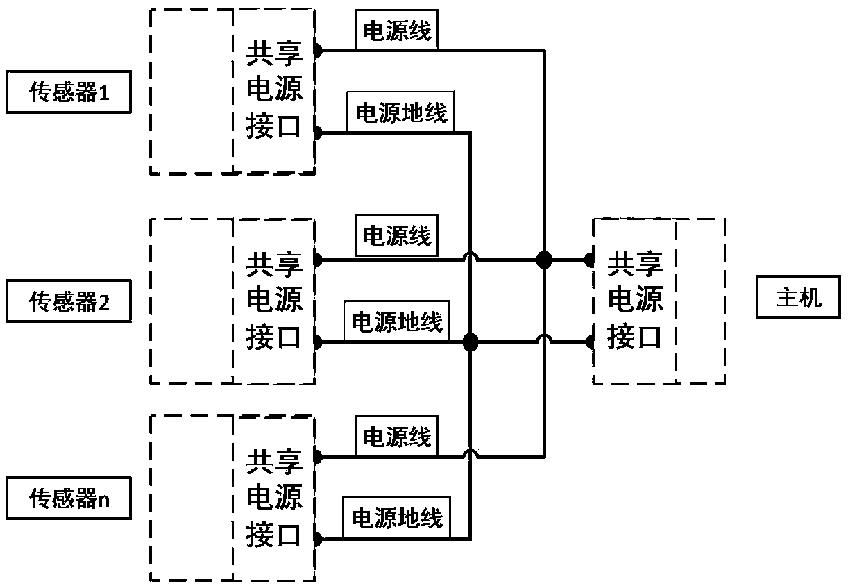
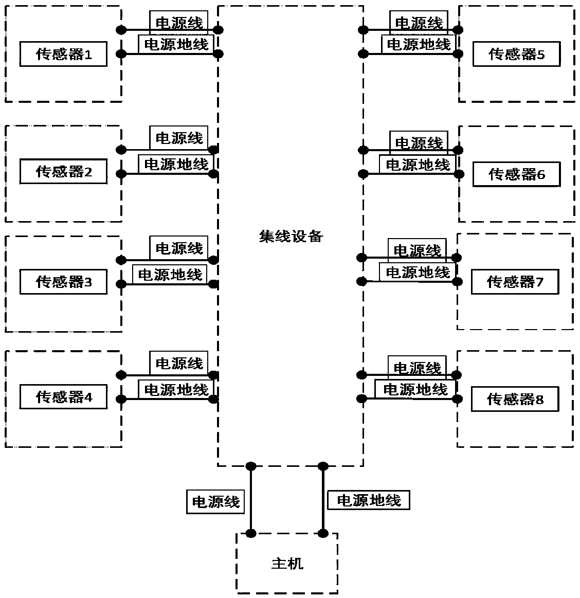
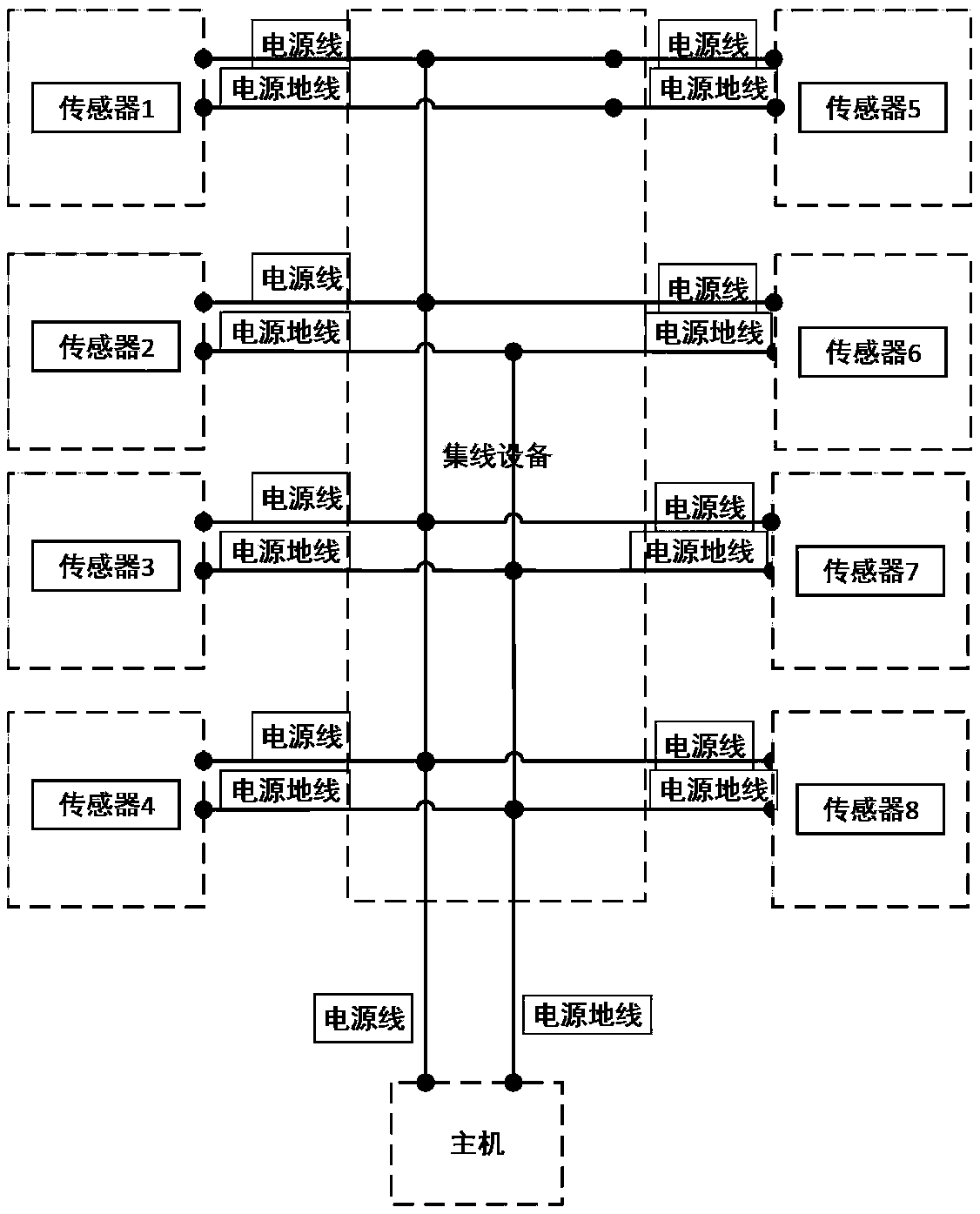
[0037] The core of the present invention is to provide a railway freight car fault diagnosis system based on power sharing. Through the power sharing between the internal sensors, between the sensors and the host, and between the hosts, each sensor and the host can maintain a relatively stable Work under voltage state to improve power generation stability and device reliability.

[0038] In order to make the objectives, technical solutions, and advantages of the embodiments of the present invention clearer, the technical solutions in the embodiments of the present invention will be described clearly and completely in conjunction with the accompanying drawings in the embodiments of the present invention. Obviously, the described embodiments It is a part of the embodiments of the present invention, not all the embodiments. Based on the embodiments of the present invention, all other embodiments obtained by those of ordinary skill in the art without creative work shall fall within t...


PUM


Abstract

The invention discloses a railway truck fault diagnosis system on the basis of power sharing. The railway truck fault diagnosis system comprises N sensors, M main units and connecting circuits. The sensors and / or the main units have power generation functions; the N and the M are positive integers; power sharing ends of the N sensors and power sharing ends of the various main units are communicated with one another via the connecting circuits; the sensors with the power generation functions and / or the main units with the power generation functions are provided with anti-backward assemblies, and the anti-backward assemblies are arranged between output ends of power generation assemblies of the sensors with the power generation functions and / or the main units with the power generation functions and the power sharing ends of the sensors with the power generation functions and / or the main units with the power generation functions; local energy dissipation circuits are connected with the power sharing ends of the sensors and the main units. The railway truck fault diagnosis system has the advantages that the various sensors and the main units can keep in relatively stable voltage statesto work by the aid of power sharing between the various internal sensors, between the sensors and the main units and between the main units, and accordingly the power generation stability and the reliability of devices can be improved.

Description

Technical field [0001] The invention relates to the technical field of detection of transportation equipment, in particular to a railway freight car fault diagnosis system based on power sharing. Background technique [0002] With the rapid development of China's railway freight transport in the direction of heavy load and speed, higher requirements have been placed on the transportation safety of railway freight cars. In order to ensure the transportation safety of railway freight cars, fault diagnosis devices need to be used to monitor and diagnose freight cars online. The fault diagnosis device is installed on the truck and consists of sensors, host and connecting cables. However, because the railway freight car is not charged except for the head of the railway freight car, the fault diagnosis device installed in the vehicle cannot work by connecting to the power supply of the vehicle. Therefore, the fault diagnosis device is needed to solve the self-powered problem. [0003] ...

Claims


Application Information

Patent Timeline
Patent Type & Authority Applications(China)
IPC IPC(8): G01R31/00
CPCG01R31/008
Inventor 唐德尧汪传文
Owner TANGZHI SCI & TECH HUNAN DEV CO LTD
Learn More