Inductive power supply with device identification

a technology of inductive power supply and device identification, which is applied in the direction of battery data exchange, exchanging data chargers, transportation and packaging, etc., can solve the problems of complicated problems and limited success of conventional systems, and achieve the effect of convenient identification of fault conditions, simple and effective methods and apparatuses, and efficient powering of remote devices

Active Publication Date: 2019-09-19
PHILIPS IP VENTURES BV
View PDF0 Cites 1 Cited by
  • Summary
  • Abstract
  • Description
  • Claims
  • Application Information

AI Technical Summary

Benefits of technology

[0016]The present invention provides a simple and effective method and apparatus for identifying remote devices. The lookup table permits the AIPS to retrieve information regarding the remote devices, such as normal operating parameters. This allows the AIPS to more efficiently power the remote device and to more readily identify fault conditions. In applications where a single resonant frequency does not provide a sufficient number of unique identifications, each device may be provided with a pattern of identification frequencies. In applications where a remote device inherently includes a uniquely identifying resonant frequencies (or frequency pattern), the present invention requires no modification to the remote device. In applications where a remote device does not include an inherent uniquely identifying resonant frequency, the remote device may be provide with one or more identification capacitors that provide the remote device with an identification frequency or an identification frequency pattern. In another aspect, the present invention provides a set of standards from which a class of remote devices may be identified by predetermined identification frequencies. This permits intelligent operation of the

Problems solved by technology

Conventional systems have met with limited success as a result of practical limitations on pre-existing inductive technology.
These problems are complicated by the fact that different remote devices typically operate within different parameters.

Method used


Image

  • Inductive power supply with device identification
  • Inductive power supply with device identification
  • Inductive power supply with device identification

Examples


Embodiment Construction

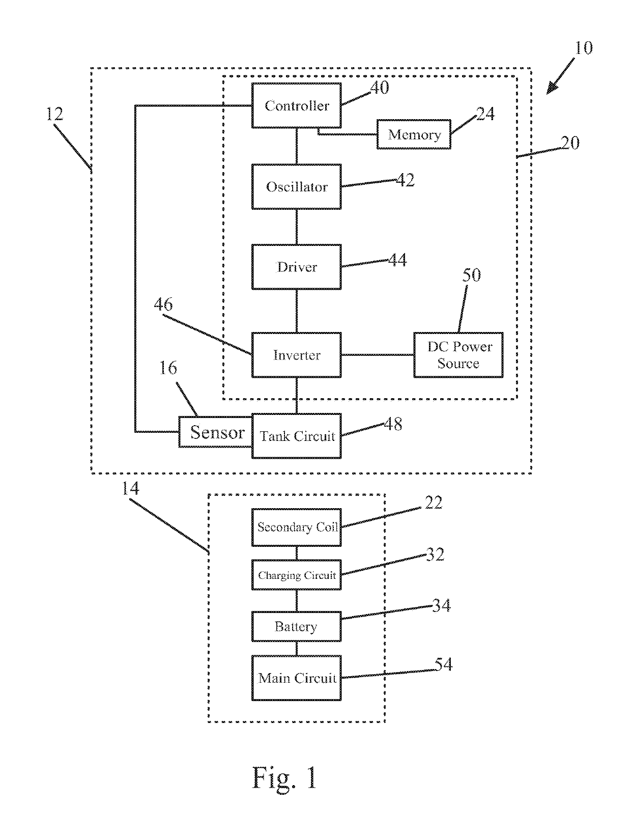
[0026]An inductive power supply system in accordance with an embodiment of the present invention is shown in FIG. 1. The inductive power supply system 10 generally includes an adaptive inductive power supply (“AIPS”) 12 and one of a plurality of remote devices 14. The

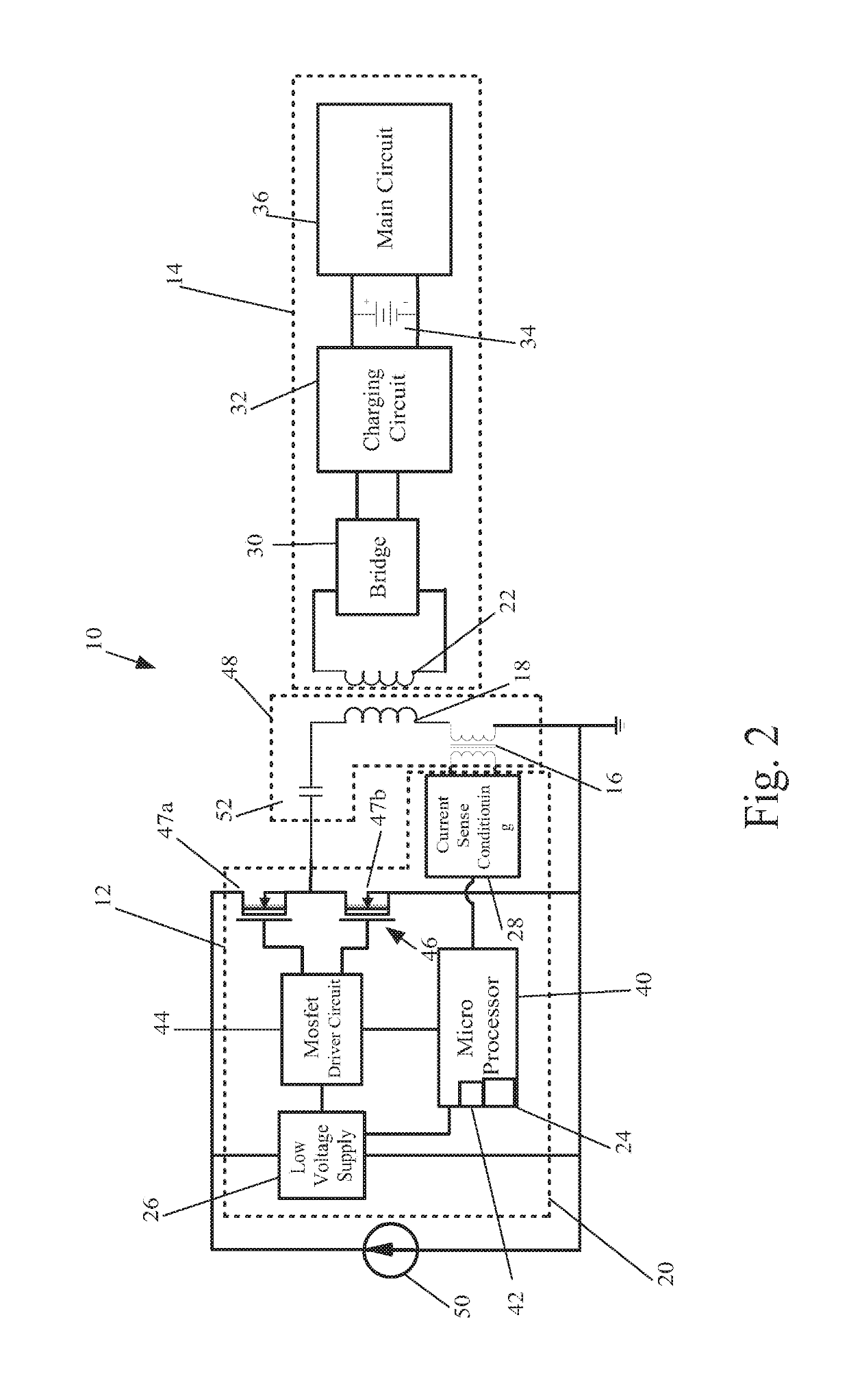
[0027]AIPS 12 generally includes a tank circuit 48 with a primary coil 18 (See FIG. 2) capable of inductively transmitting power. The AIPS also includes a controller 20 for selectively controlling the frequency at which power is generated by the primary coil 18, and a sensor 16 capable of sensing reflected impedance from a remote device 14. The AIPS 12 is intended for use with one or more remote devices 14, each of which has a unique resonant frequency or unique pattern of resonant frequencies. In operation, the AIPS 12 applies power to the primary 18 at an identification frequency and then evaluates the reflected impendence of the remote device 14 using the current sensor 16. If the remote device 14 has a resonant freq...


PUM


Abstract

An inductive power supply system to identify remote devices using unique identification frequencies. The system includes an AIPS and a tank circuit capable of inductively providing power to a remote device at different frequencies, and a sensor for sensing the reflected impedance of the remote device at tank circuit. The system further includes a plurality of different remote devices, each having a unique resonance frequency. In operation, the AIPS is capable of identifying the type of remote device present in the inductive field by applying power to a remote device at a plurality of unique identification frequencies until the remote device establishes resonance in response to one of the identification frequencies. The AIPS includes a controller that recognizes when resonance has been established by evaluating sensor data, which is representative of the reflected impedance of the remote device. Once the identity of a remote device is determined, the AIPS may pull operating parameters for the remove device from memory to ensure efficient operation and to assist in recognizing fault conditions.

Description

CROSS-REFERENCE TO PRIOR APPLICATIONS[0001]This application is a continuation application of U.S. application Ser. No. 15 / 059,344, filed on Mar. 3, 2016, which claims the benefit of U.S. application Ser. No. 13 / 323,126, filed on Dec. 12, 2011 and Issued on Apr. 19, 2016 as U.S. Pat. No. 9,318,912, which claims the benefit of U.S. application Ser. No. 13 / 166,187, filed on Jun. 22, 2011 and Issued on Jan. 17, 2012, as U.S. Pat. No. 8,097,984, which claims the benefit of U.S. application Ser. No. 11 / 965,085, filed on Dec. 27, 2007 and Issued on Aug. 2, 2011 as U.S. Pat. No. 7,989,986, which claims the benefit of U.S. application Ser. No. 11 / 388,142, filed on Mar. 23, 2006 and Issued on Apr. 8, 2008 and claims the benefit of Provisional application No. 60 / 883,127, filed on Jan. 2, 2007. These applications are hereby incorporated by reference herein.[0002]The present invention relates to inductive power supply systems, and more particularly to an apparatus and method for inductive poweri...

Claims


Application Information

Patent Timeline
Patent Type & Authority Applications(United States)
IPC IPC(8): H02J50/12H02J7/02
CPCH02J50/12H02J7/025H02J50/80H02J50/40H02J7/00034H04B5/0037H02J50/10H02J50/27
Inventor BAARMAN, DAVID W.MOLLEMA, SCOTT A.
Owner PHILIPS IP VENTURES BV
Why Eureka
Try Eureka