Liquid crystal light-adjusting film, backlight module and manufacturing method of liquid crystal light-adjusting film

Active Publication Date: 2019-10-03
CORETRONIC
View PDF3 Cites 1 Cited by
  • Summary
  • Abstract
  • Description
  • Claims
  • Application Information

AI Technical Summary

Benefits of technology

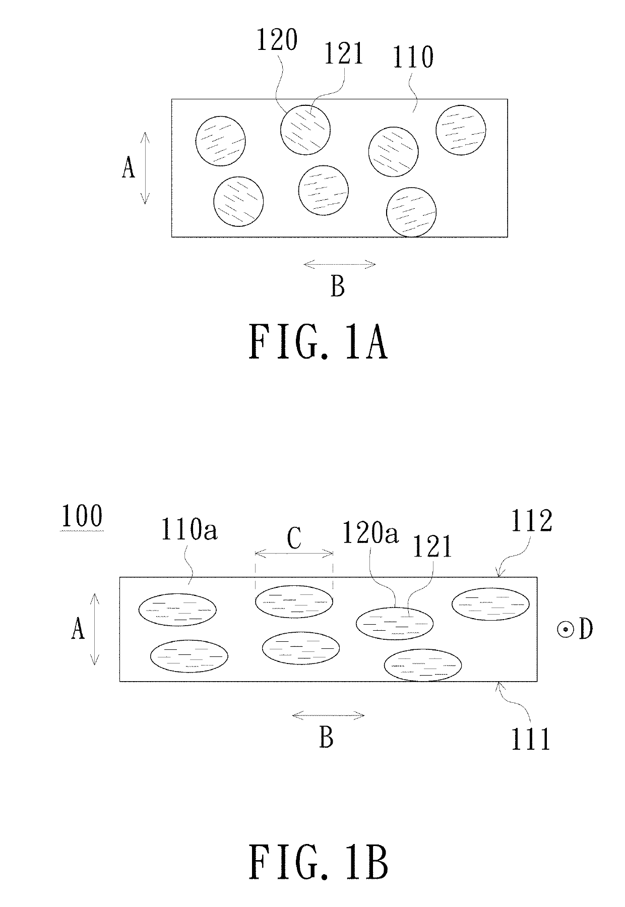
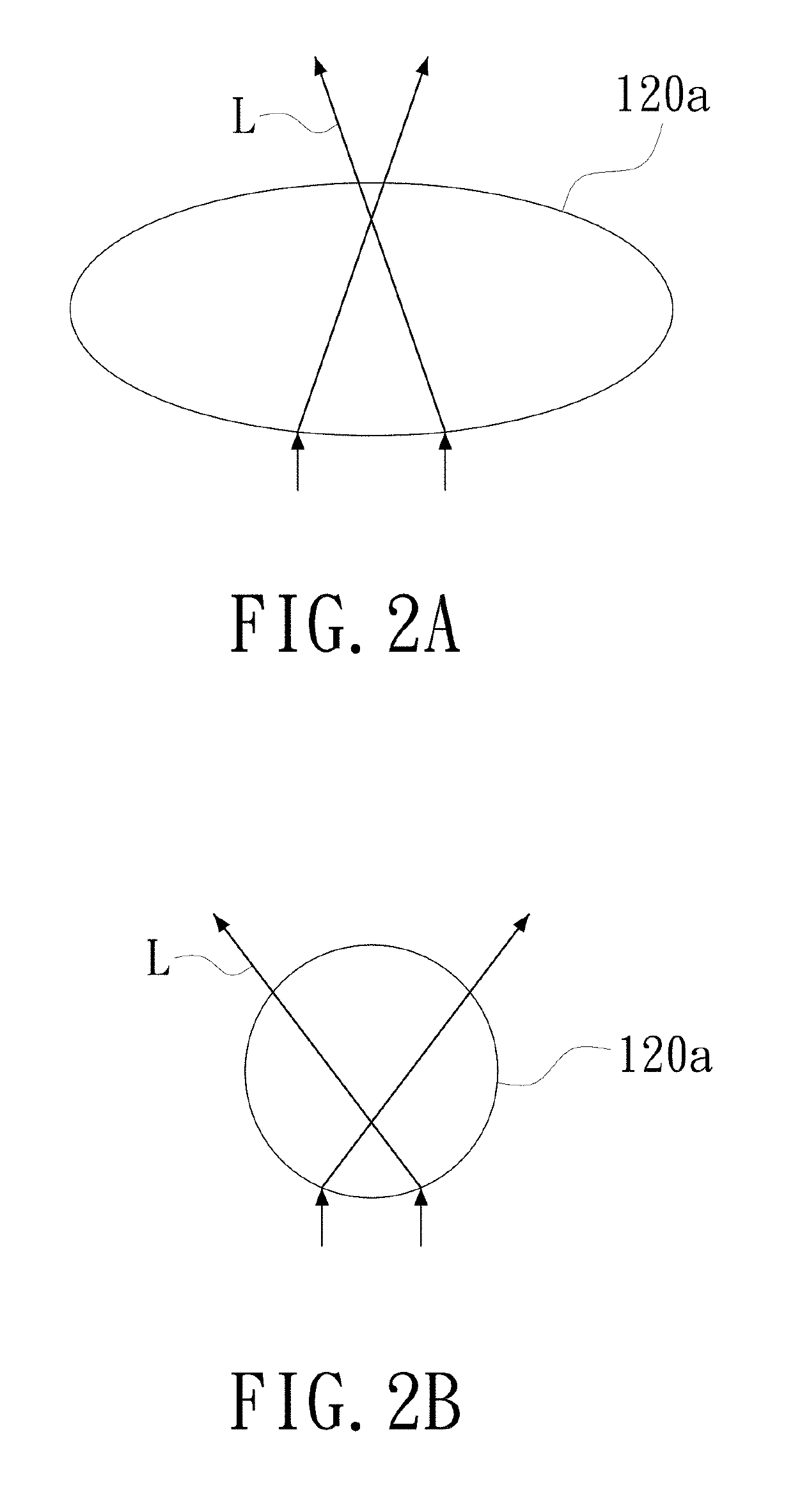
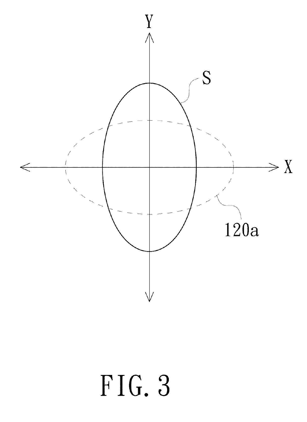
The invention is a liquid crystal light-adjusting film and a method to manufacture it. The film has an elliptical crystal cell with different surface curvatures that causes an anisotropic scattering of light, resulting in an anti-reflection or anti-peeping effect. The film can provide functional design requirements for anti-reflection or anti-peeping, and the backlight module utilizing the film can achieve these requirements.

Problems solved by technology

Diffusion plates for automotive display are known to have a large thickness, which cannot meet the requirements for thin and lightweight models.
Polymer dispersed liquid crystals (PDLC) film has an excellent effect of switching between transparent and matte surfaces, but it cannot achieve the scattering function in specific directions.

Method used


Image

  • Liquid crystal light-adjusting film, backlight module and manufacturing method of liquid crystal light-adjusting film
  • Liquid crystal light-adjusting film, backlight module and manufacturing method of liquid crystal light-adjusting film
  • Liquid crystal light-adjusting film, backlight module and manufacturing method of liquid crystal light-adjusting film

Examples


Embodiment Construction

[0025]In the following detailed description of the preferred embodiments, reference is made to the accompanying drawings which form a part hereof, and in which is shown by way of illustration specific embodiments in which the invention may be practiced. In this regard, directional terminology, such as “top”, “bottom”, “front”, “back”, etc., is used with reference to the orientation of the Figure(s) being described. The components of the invention can be positioned in a number of different orientations. As such, the directional terminology is used for purposes of illustration and is in no way limiting. On the other hand, the drawings are only schematic and the sizes of components may be exaggerated for clarity. It is to be understood that other embodiments may be utilized and structural changes may be made without departing from the scope of the invention. Also, it is to be understood that the phraseology and terminology used herein are for the purpose of description and should not b...


PUM

PropertyMeasurementUnit
Thicknessaaaaaaaaaa
Thicknessaaaaaaaaaa
Refractive indexaaaaaaaaaa

Abstract

A liquid crystal light-adjusting film includes a polymer material substrate and a plurality of elliptical crystal cells. The polymer material substrate has a light incident surface and a light exiting surface opposite to each other. A direction from the light incident surface to the light exiting surface is a thickness direction of the polymer material substrate. The elliptical crystal cells are disposed in the polymer material substrate. A long axis direction of each of the elliptical crystal cells is arranged along a first direction perpendicular to the thickness direction, and each of the elliptical crystal cells comprises a plurality of liquid crystal molecules. A manufacturing method of the liquid crystal light-adjusting film and a backlight module using the liquid crystal light-adjusting film are also provided.

Description

CROSS-REFERENCE TO RELATED APPLICATION[0001]THIS APPLICATION CLAIMS THE PRIORITY BENEFIT OF CHINA APPLICATION (CN201810258258.X FILED ON 2018 Mar. 27). THE ENTIRETY OF THE ABOVE-MENTIONED PATENT APPLICATION IS HEREBY INCORPORATED BY REFERENCE HEREIN AND MADE A PART OF THIS SPECIFICATION.FIELD OF THE INVENTION[0002]The invention relates to a light-adjusting film, and more particularly to a liquid crystal light-adjusting film, a manufacturing method for the same, and a backlight module using the liquid crystal light-adjusting film.BACKGROUND OF THE INVENTION[0003]As the demand for electronic parts of vehicles has increased year by year, various display systems for vehicles have been developed successively. There have also been considerable developments in the field of automotive displays. However, due to the stricter regulations for vehicle equipment, how to meet the application requirements of the driver and comply with the standards at the same time will be the focus of future devel...

Claims


Application Information

Patent Timeline
IPC IPC(8): F21V8/00G02B1/111
CPCG02B1/111G02B6/0051G02F1/1334G02B5/3016G02B6/0066C09K2323/06G02B6/0055C09K2323/03G02B6/0061G02F1/13347G02F1/133638
Inventor HSU, HSIUNG-CHUNTSANG, CHIH-JENCHEN, PING-YENGFANG, CHONG-YANG
Owner CORETRONIC
Why Eureka
Try Eureka