Fuel cell activation method

a fuel cell and activation method technology, applied in the direction of fuel cell control, fuel cell, solid electrolyte fuel cells, etc., can solve the problems of low material cost of fuel cells and insufficient power generation properties, and achieve excellent power generation properties, low overvoltage properties, and improved proton conduction.

Active Publication Date: 2019-10-03
HONDA MOTOR CO LTD
View PDF0 Cites 6 Cited by
  • Summary
  • Abstract
  • Description
  • Claims
  • Application Information

AI Technical Summary

Benefits of technology

[0008]A principal object of the present invention is to provide a simple method capable of easily activating a fuel cell.
[0011]In both of the first and second methods, particularly an oxide covering a surface of a metal catalyst contained in a catalyst layer in the cathode is removed. Furthermore, in an oxidation process, a catalyst carrier material is subjected to a high electric potential, and a surface area of the catalyst carrier material is increased. Thus, an area of a reaction field containing oxygen atoms, protons, and electrons is increased. As a result, an active surface area of the metal catalyst in the reaction field is increased.
[0013]Furthermore, because the water is transferred as described above, the electrolyte membrane is in a sufficiently wet state. Consequently, the proton conduction is improved, and the fuel cell exhibits an excellent power generation property.
[0014]In addition, only the hydrogen participates in the hydrogen pumping reaction. A low overvoltage property of the hydrogen allows a high current to continuously flow in the fuel cell. Consequently, the time required for the activation treatment can be shortened.

Problems solved by technology

A large amount of the noble metal such as platinum for the metal catalyst results in a high material cost for the fuel cell.
Therefore, a sufficient power generation property is hardly obtained until a surface of the metal catalyst is washed with water generated in the power generation process.

Method used


Image

  • Fuel cell activation method
  • Fuel cell activation method
  • Fuel cell activation method

Examples


first embodiment

[0039]An example of the fuel cell 10 activation method of the first embodiment will be described below. In the following example, a moist hydrogen gas is used as the fuel gas, and a moist nitrogen gas is used as the inert gas.

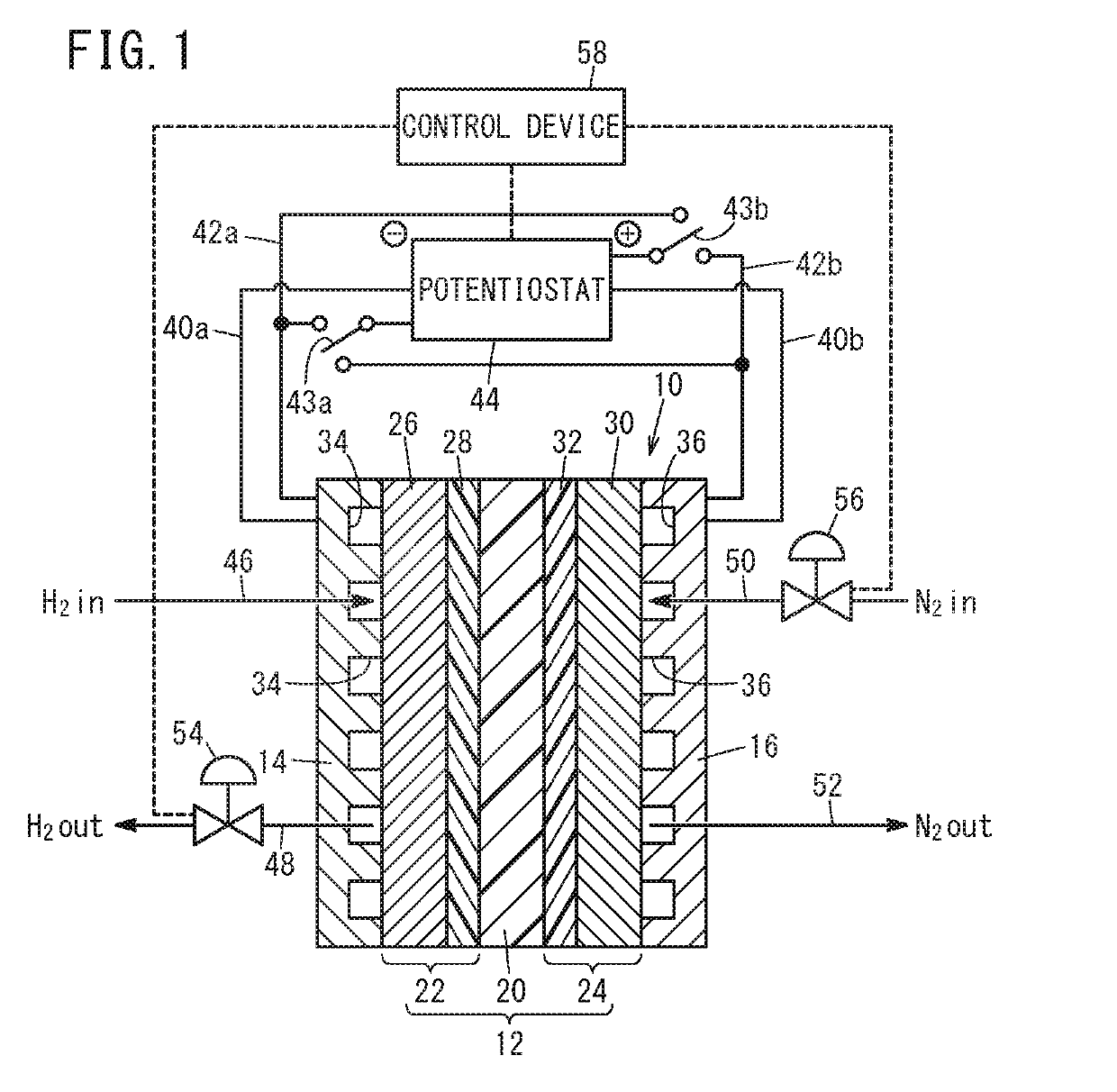
[0040]In the first embodiment, the fuel cell 10 (the unit cell or the fuel cell stack) is subjected to the activation treatment immediately after the production of the fuel cell 10. First, the anode gas supply line 46, the anode gas discharge line 48, the cathode gas supply line 50, and the cathode gas discharge line 52 are connected to the fuel cell 10 as produced, and the potentiostat 44 is electrically connected to the fuel cell 10 by the current application wires 40a, 40b and the voltage application wires 42a, 42b. Furthermore, the potentiostat 44 and the cutoff valves 54, 56 are electrically connected to a control circuit.

[0041]Then, when the cutoff valves 54, 56 are in the open states, the moist hydrogen gas is supplied to the anode 22 through the anode g...

second embodiment

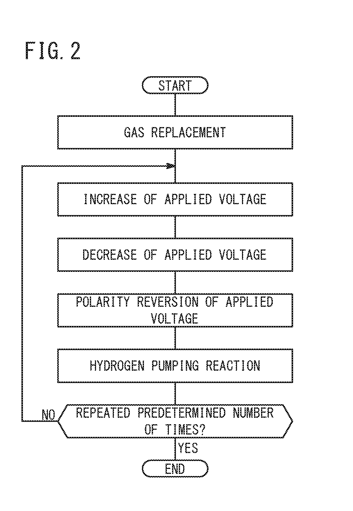
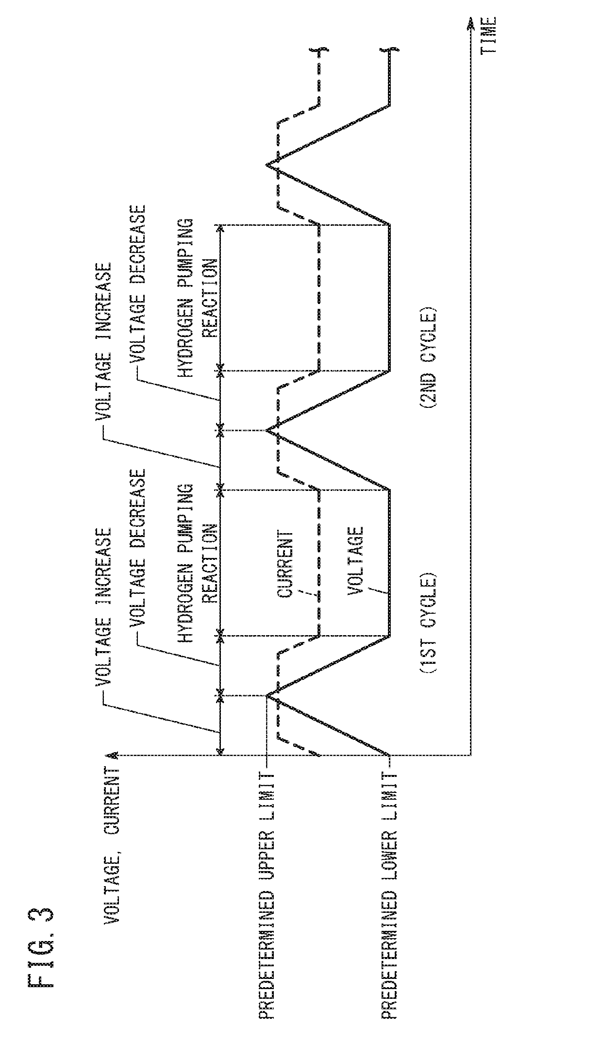
[0061]In the second embodiment, the voltage is increased to the predetermined upper limit, and then is maintained at the predetermined upper limit. Thus, the voltage maintenance step is carried out. In the voltage maintenance step, the metal catalyst in the cathode catalyst layer 32 is oxidized. For example, the voltage is maintained at the upper limit preferably for a period of 30 to 300 seconds, more preferably for a period of 40 to 120 seconds.

[0062]After the voltage maintenance step is carried out for a predetermined period, the voltage decrease to a predetermined lower limit is started. Thus, the voltage decrease step is carried out. The voltage decrease step in the second embodiment may be carried out in the same manner as that in the first embodiment. In the voltage decrease step, it is preferred that the voltage is gradually decreased (see FIG. 5).

[0063]After the voltage is decreased to the predetermined lower limit (e.g. 0 V), it is preferred that a hydrogen pumping reactio...


PUM

PropertyMeasurementUnit
voltageaaaaaaaaaa
voltageaaaaaaaaaa
voltageaaaaaaaaaa

Abstract

A voltage is applied between an anode and a cathode in a fuel cell. The voltage is increased to a predetermined upper limit, and then decreased to a predetermined lower limit. The voltage increase and decrease are repeated a predetermined number of times.

Description

CROSS-REFERENCE TO RELATED APPLICATION[0001]This application is based upon and claims the benefit of priority from Japanese Patent Applications No. 2018-065937 filed on Mar. 29, 2018 and No. 2018-065946 filed on Mar. 29, 2018, the contents all of which are incorporated herein by reference.BACKGROUND OF THE INVENTIONField of the Invention[0002]The present invention relates to a method for activating a fuel cell having an electrolyte membrane containing a solid polymer.Description of the Related Art[0003]A so-called solid polymer electrolyte fuel cell, which has a membrane electrode assembly containing an anode and a cathode with a solid polymer electrolyte membrane interposed therebetween, has been known as a type of fuel cell.[0004]Each of the anode and the cathode has a catalyst layer containing a metal catalyst of a noble metal such as platinum. Immediately after the production of a fuel cell stack, the catalyst layer does not exhibit a sufficient activity, and therefore the fuel ...

Claims


Application Information

Patent Timeline
Patent Type & Authority Applications(United States)
IPC IPC(8): H01M8/04858H01M8/04223H01M8/04089H01M8/04302H01M8/12
CPCH01M8/12H01M8/04302H01M8/04873H01M2008/1095H01M8/04223H01M8/04089H01M8/04902H01M8/04298H01M8/0488Y02E60/50
Inventor TOYOTA, SHOHEIYOSHIDA, HIROMICHIKAJI, HAYATO
Owner HONDA MOTOR CO LTD
Why Eureka
Try Eureka