Storage rack guard drop-in bracket

a technology for storage racks and brackets, which is applied in the field of storage rack guard brackets, can solve the problems of large number of storage rack guard bracket systems, damage to personnel, and/or risks, and achieve the effect of a greater cross-sectional area

Active Publication Date: 2019-10-10
SPACEGUARD PROD INC
View PDF0 Cites 4 Cited by
  • Summary
  • Abstract
  • Description
  • Claims
  • Application Information

AI Technical Summary

Benefits of technology

[0004]an example apparatus includes a bracket having a rack attachment member and a guard attachment member, an upper rack engagement tab in a lower rack engagement tab, where each engagement tab is coupled to the rack attachment member, and each engagement tab includes a stem portion coupled to the rack attachment member in a head portion having a greater cross-sectional area than the stem portion. The example apparatus includes a rack attachment member defining a lock pin hole positioned in proximity to one of the upper rack engagement tab and a lower rack engagement tab, where the lock pin hole is sized and positioned such that the lock pin hole provides sufficient cross-sectional area within a rack engagement distance to allow passage of a bracket lock pin through the lock pin hole within the rack engagement distance, and where the rack engagement distance is determined from a vertically lowest point of the lower rack engagement tab or the upper rack engagement tab. The example apparatus further includes a bracket lock pin having a stabilizing leg coupled to a lock pin head, the stabilizing leg having a diameter less than a diameter of the lock pin hole, and where the stabilizing leg has a geometry such that the lock pin head is urged toward the lock pin hole in the stabilizing leg is passed through the lock pin hole.

Problems solved by technology

Storage rack guards prevent stored items from inadvertently falling from storage racks, causing damage and / or risks to personnel.
Previously known storage rack guard bracket systems suffer from a number of drawbacks, including costly and time consuming installation, complexity of design, and expensive parts included as part of the design.
Additionally, storage racks, especially in large warehouse environments, may be at a height or otherwise positioned in inconvenient installation environments, which increases the risk and difficulty of installing the storage rack guard.

Method used


Image

  • Storage rack guard drop-in bracket
  • Storage rack guard drop-in bracket
  • Storage rack guard drop-in bracket

Examples


Embodiment Construction

[0033]For the purposes of promoting an understanding of the principles of the invention, reference will now be made to specific embodiments illustrated in the drawings and specific language will be used to describe the same. It will nevertheless be understood that no limitation of the scope of the invention is thereby intended, and any alterations and further modifications in the illustrated embodiments, and any further applications of the principles of the invention as illustrated therein as would normally occur to one skilled in the art to which the invention relates are contemplated herein.

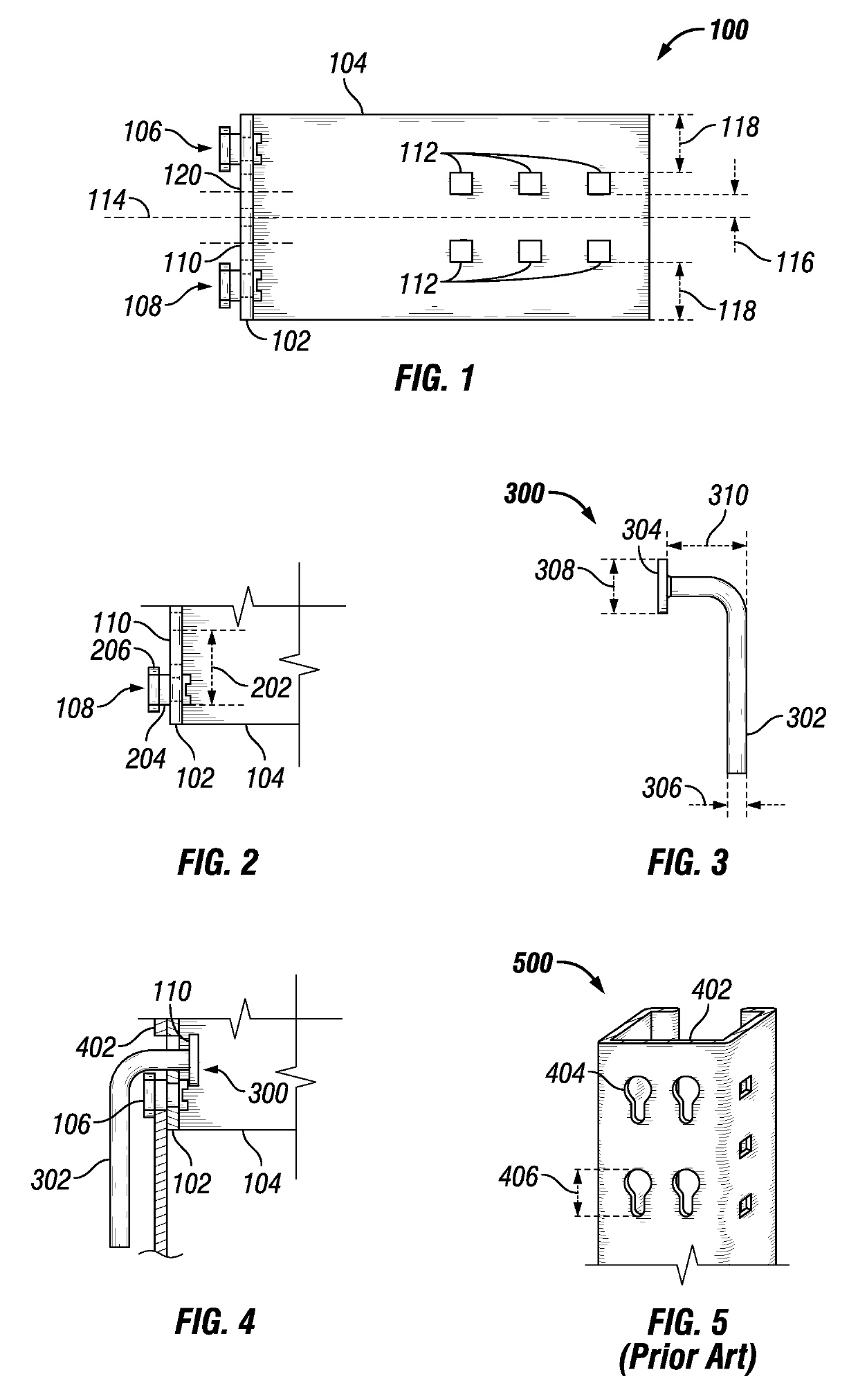
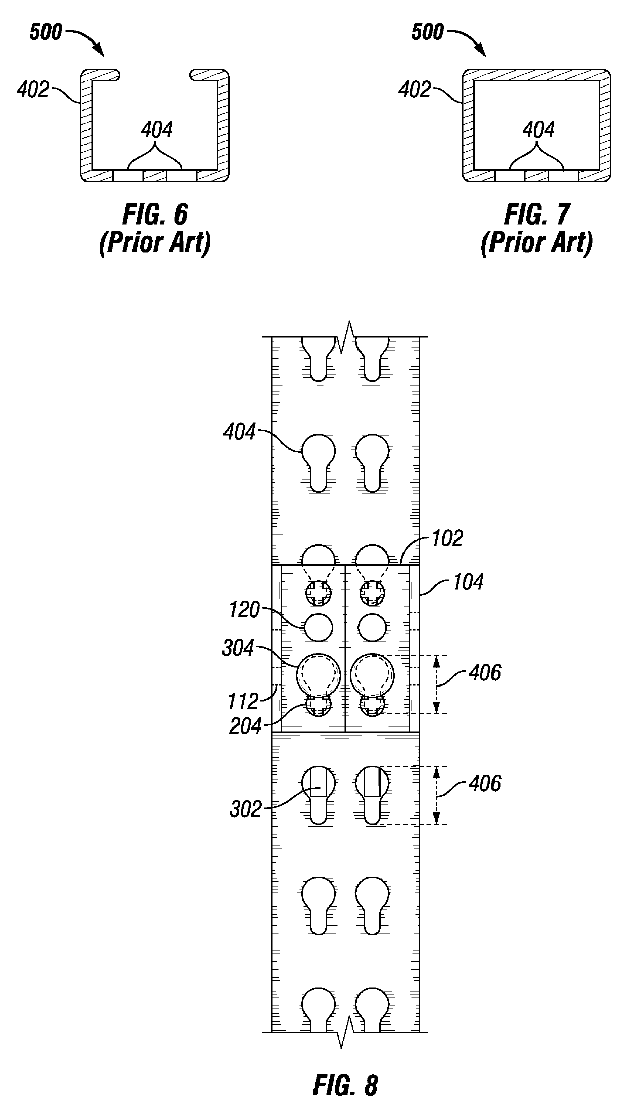
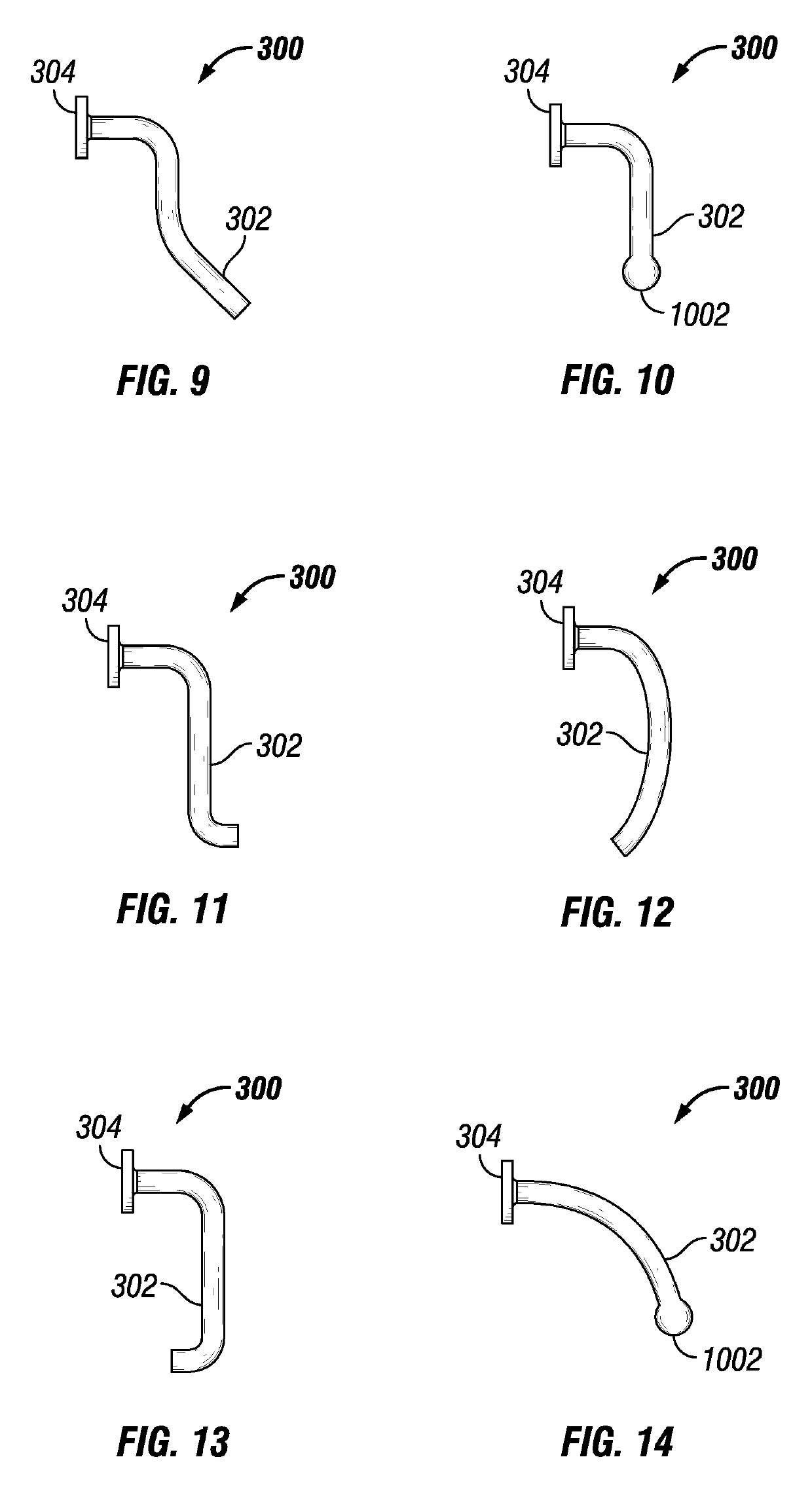
[0034]The disclosure is directed to a drop-in bracket that can be installed readily and without the use of tools. Certain applications for the drop-in bracket are described as a storage rack guard, although the disclosure is not limited to such embodiments. Any device may be mounted on the drop-in bracket, including at least a rack guard, a screen guard, a pallet protector, a rack back backing,...


PUM


Abstract

An example apparatus includes a bracket having a rack attachment member and a guard attachment member, and upper and lower engagement tabs that are coupled to the rack attachment member and have a stem portion and a head portion. The rack attachment member has a lock pin hole above the lower rack engagement tab. The lock pin hole is sized and positioned to provide sufficient cross-sectional area within a rack engagement distance to allow passage of a bracket lock pin therethrough within the rack engagement distance. The apparatus further includes a bracket lock pin having a stabilizing leg coupled to a lock pin head, where the stabilizing leg fits through the lock pin hole and the lock pin head does not. The stabilizing leg urges the lock pin head toward the lock pin hole when the stabilizing leg is passed through the lock pin hole.

Description

STATEMENT OF PRIORITY[0001]This application is a bypass continuation of International Application PCT / US2016 / 068524 entitled “STORAGE RACK GUARD DROP-IN BRACKET”, filed Dec. 23, 2016, published as WO 2018 / 118083 on Jun. 28, 2018 (SPGD-0001-WO).BACKGROUNDField[0002]This disclosure relates to, without limitation, storage rack guard brackets.Description of Related Art[0003]Storage rack guards prevent stored items from inadvertently falling from storage racks, causing damage and / or risks to personnel. Previously known storage rack guard bracket systems suffer from a number of drawbacks, including costly and time consuming installation, complexity of design, and expensive parts included as part of the design. Additionally, storage racks, especially in large warehouse environments, may be at a height or otherwise positioned in inconvenient installation environments, which increases the risk and difficulty of installing the storage rack guard.SUMMARY[0004]an example apparatus includes a br...

Claims


Application Information

Patent Timeline
Patent Type & Authority Applications(United States)
IPC IPC(8): A47B96/06A47B96/20A47B57/22
CPCA47B96/20A47B57/22A47B96/06
Inventor MURPHY, EDWARD M.JUMP, SCOTT A.ROBERTS, CHRISTOPHER LEE
Owner SPACEGUARD PROD INC
Why Eureka
Try Eureka