Valve opening/closing timing control device

Inactive Publication Date: 2017-01-12
AISIN SEIKI KK
View PDF1 Cites 0 Cited by
  • Summary
  • Abstract
  • Description
  • Claims
  • Application Information

AI Technical Summary

Benefits of technology

[0037]With this characterizing feature, the fluid charged into the advance angle chamber will move to the retard angle chamber via the second flow passage, the communication passage and the first flow passage. In this, since the passage cross sectional area of the second flow passage communicated to the advance angle chamber is smaller than the passage cross sectional area of the first flow passage, there occurs no reduction in the charging speed of the fluid to the advance angle chamber. Next, when the fluid moves to the retard

Problems solved by technology

At the time of starting an engine, if a relative rotational phase of a driven-side rotating body relative to a drive-side rotating body is set to a most retarded angle phase, with resultant retardation of the closing timing of an intake valve, mixture gas present inside a combustion chamber can flow reversely into an intake pipe, thus leading to disadvantageous reduction in a compression ratio inside the combustion chamber, which i

Method used


Image

  • Valve opening/closing timing control device
  • Valve opening/closing timing control device
  • Valve opening/closing timing control device

Examples


first embodiment

1. First Embodiment

[0047]Next, a first embodiment of the disclosure will be explained with reference to the drawings.

[Basic Configuration]

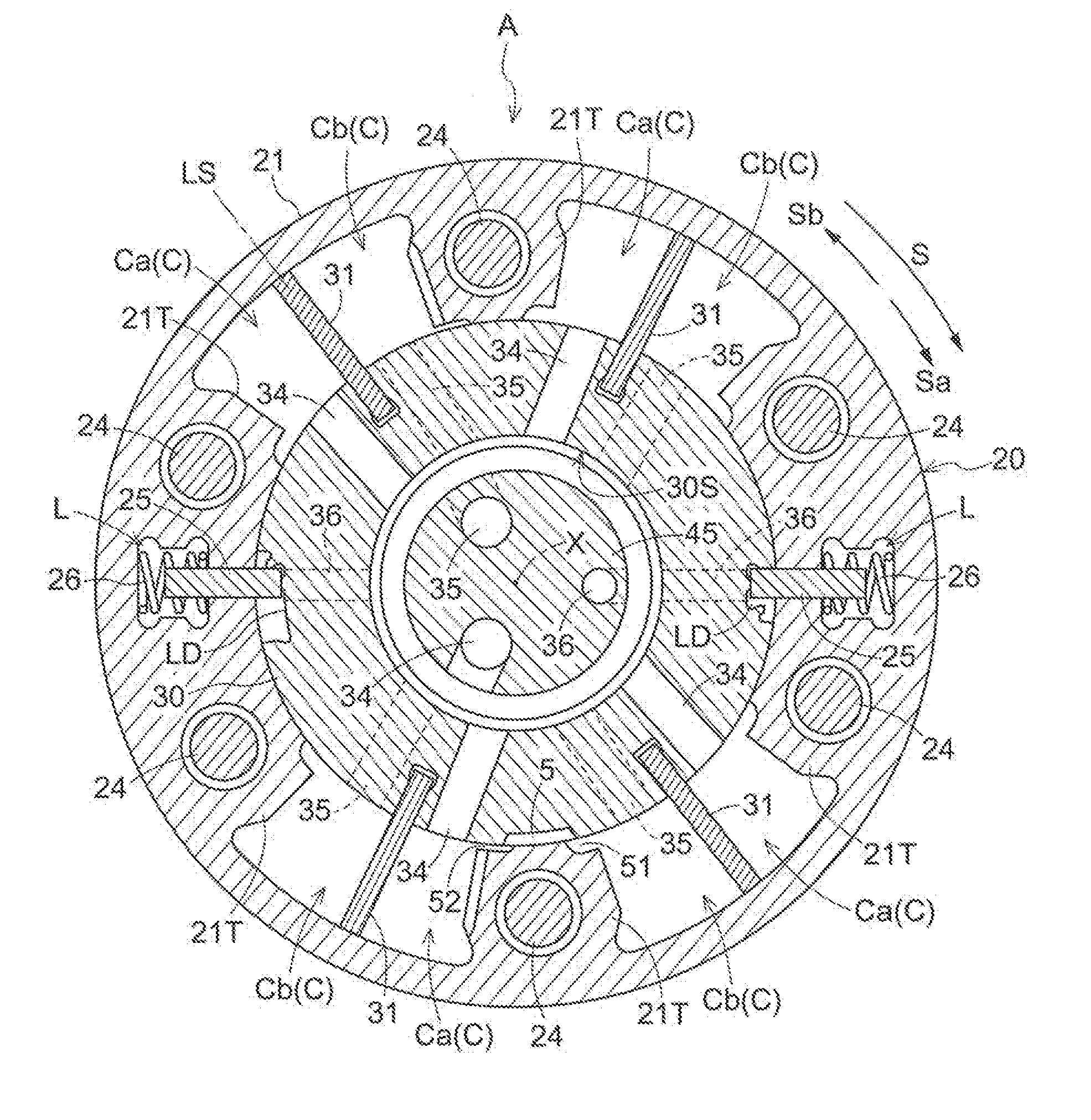
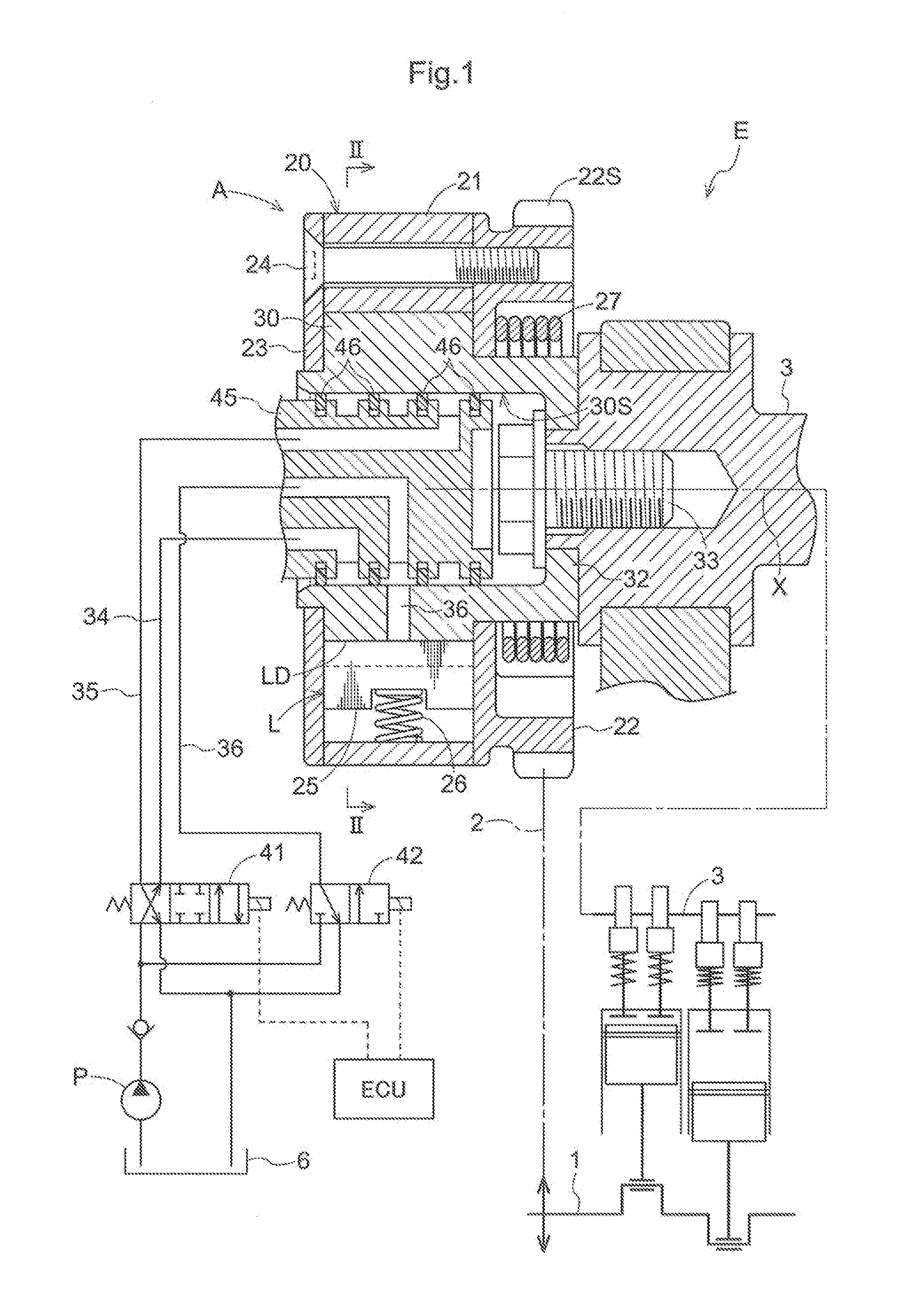
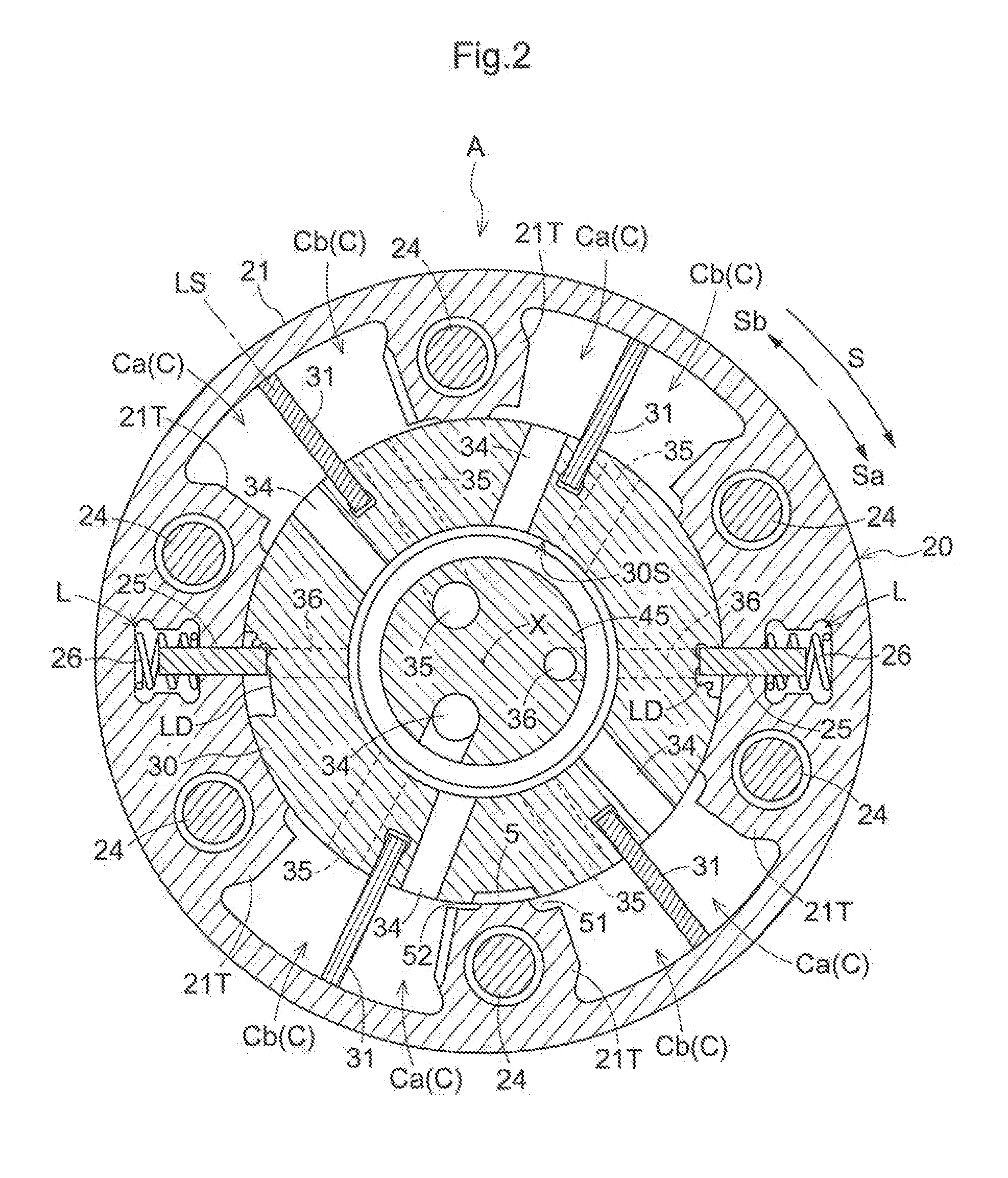
[0048]FIG. 1 and FIG. 2 show a valve opening / closing timing control device A relating to the present disclosure. This valve opening / closing timing control device A includes an outer rotor 20 as a “drive-side rotating body”, an inner rotor 30 as a “driven-side rotating body”, and an intermediate lock mechanism L capable of being switched over between a locked state in which a relative rotational phase of the inner rotor 30 relative to the outer rotor 20 (this will be referred to as “relative rotational phase” hereinafter) is restrained to an intermediate lock phase LS between a most advanced angle phase and a most retarded angle phase, and an unlocked state in which the above restraint is released.

[0049]The outer rotor 20 includes a cylindrical rotor body 21 (an example of “outer circumferential wall portion”), a disc-like rear plate 22 (an example...

second embodiment

2. Second Embodiment

[0071]A second embodiment will now be explained regarding its differences from the first embodiment only, with reference to FIG. 7. Incidentally, for better understanding of the drawing, the following explanation will be made with denoting the same members as the first embodiment with the same reference marks / numerals.

[0072]In this embodiment, the communication passage 5 is formed by cutting out a portion of the outer rotor 20 which portion comes into opposition to the outer circumferential end face of the vane portion 31 under the locked state. This cutout can be formed at a corner portion or an inner face of the outer rotor 20. In this case, at the time of starting the engine E, with the effect of the centrifugal force associated with rotation of the outer rotor 20, the oil of the advance angle chamber Ca moves toward the outer circumferential side and at the same time it starts moving to the retard angle chamber Cb via the communication passage 5. Namely, the ...

third embodiment

3. Third Embodiment

[0073]A third embodiment will now be explained regarding its differences from the first embodiment only, with reference to FIG. 8. Incidentally, for better understanding of the drawing, the following explanation will be made with denoting the same members as the first embodiment with the same reference marks / numerals.

[0074]In this embodiment, the communication passage 5 is formed by cutting out a portion of one of the rear plate 22 and the front plate 23 to which portion the vane portion 31 under the locked state is projected in the direction of the rotational axis X. FIG. 8 shows the rear plate 22 with a portion thereof being cut out.

[0075]On the near side in the illustration, the advance angle chamber Ca is present and on the far side in the illustration across the vane portion 31, the retard angle chamber Cb is present. Namely, when the intermediate lock mechanism L is under the locked state, the communication passage 5 establishes communication between the adv...


PUM


Abstract

Provided is a valve opening/closing timing control device that can speedily achieve a stable operation at the time of starting an engine. The device includes a drive-side rotating body that is rotated in synchronism with a crankshaft and has a plurality of projecting portions, a driven-side rotating body that has a partition portion which forms an advance angle chamber and a retard angle chamber and that is rotated together with a camshaft for valve opening/closing, an intermediate lock mechanism switchable between a locked state and an unlocked state, a pump for supplying fluid to the advance angle chamber, the retard angle chamber or the intermediate lock mechanism, and a communication passage configured to establish communication between the advance angle chamber and the retard angle chamber disposed adjacent in a circumferential direction when the intermediate lock mechanism is under the locked state.

Description

TECHNICAL FIELD[0001]This disclosure relates to a valve opening / closing timing control device having an intermediate lock mechanism for restraining a relative rotational phase of a driven-side rotating body relative to a drive-side rotating body to a phase between a most advanced angle phase and a most retarded angle phase.BACKGROUND ART[0002]At the time of starting an engine, if a relative rotational phase of a driven-side rotating body relative to a drive-side rotating body is set to a most retarded angle phase, with resultant retardation of the closing timing of an intake valve, mixture gas present inside a combustion chamber can flow reversely into an intake pipe, thus leading to disadvantageous reduction in a compression ratio inside the combustion chamber, which invites deterioration of start-up performance. On the other hand, at the time of starting the engine, if the relative rotational phase of the driven-side rotating body relative to the drive-side rotating body is set to...

Claims


Application Information

Patent Timeline
IPC IPC(8): F01L1/344
CPCF01L2001/34453F01L1/3442F01L1/46F01L2001/34423F01L2001/34459F01L2001/34463F01L2001/34466F01L2001/34473F01L2001/34476
Inventor SUZUKI, SHIGEMITSUTOMA, NAOTOMUKAIDE, HIROKI
Owner AISIN SEIKI KK
Why Eureka
Try Eureka