Busbar assembly

Inactive Publication Date: 2008-05-29
TYCO ELECTRONICS BRASIL
View PDF8 Cites 1 Cited by
  • Summary
  • Abstract
  • Description
  • Claims
  • Application Information

AI Technical Summary

Benefits of technology

[0009]One advantage of exemplary embodiments of the invention is that the conductive bar is substantially solid and does not include through-holes, thereby providing a greater cross sectional area and increasing current capacity without increasing the overall size of the conductive bar used.
[0010]Another advantage

Problems solved by technology

Furthermore, busbar assemblies are usually subjected to one or both of vibration and thermal stress during normal operating conditions.
This can l

Method used


Image

  • Busbar assembly
  • Busbar assembly
  • Busbar assembly

Examples


Example

[0025]Where like parts appear in more than one drawing, it has been attempted to use like reference numerals for clarity.

DETAILED DESCRIPTION OF EXEMPLARY EMBODIMENTS

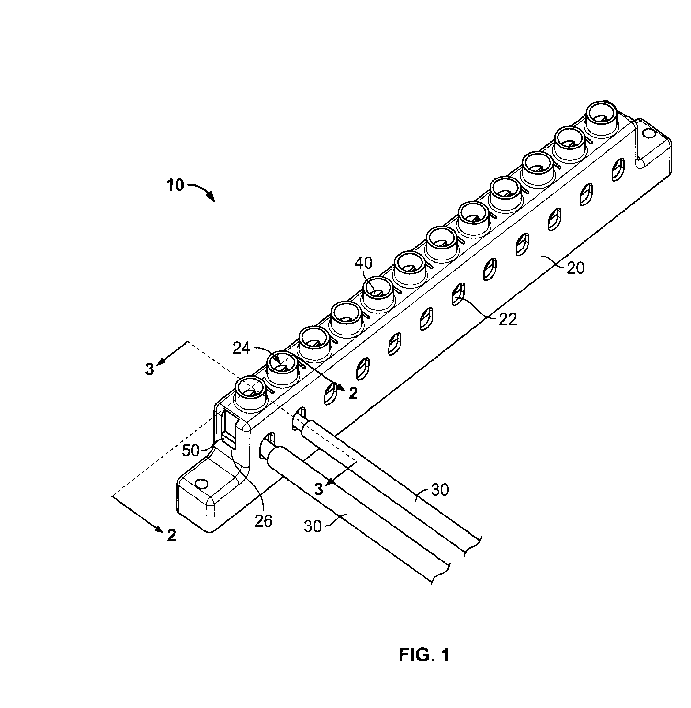
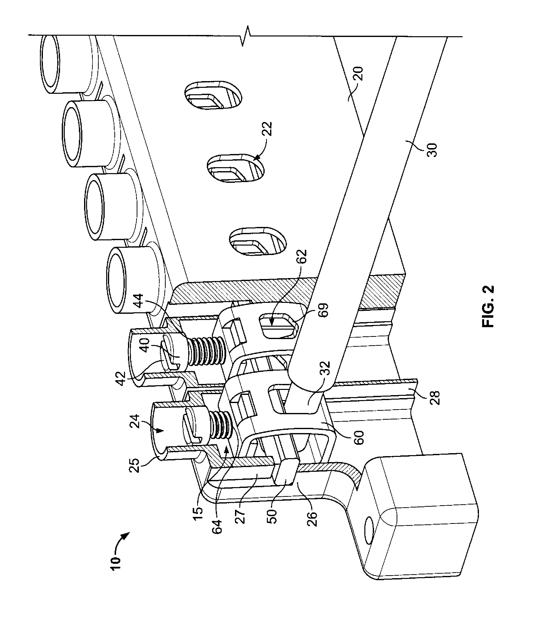
[0026]Exemplary embodiments of the invention are directed to busbar assemblies that include a cable retention system that holds electrically conductive cables in contact with a substantially solid conductive bar without the need for through-holes in the bar that decrease its current carrying capacity.

[0027]Referring to FIG. 1, a busbar assembly 10 includes an electrically insulating busbar housing 20 having a plurality of cable-receiving ports 22 for receiving conductive cables 30 to carry electric current. A substantially solid conductive bar 50 extends from a first end of the busbar housing 20 to a second end of the busbar housing 20 and completes an electric circuit between two or more cables 30 in contact with the bar 50. By “substantially solid” is meant that the conductive bar 50 has no through-holes, although pit...


PUM


Abstract

Busbar assemblies are disclosed. The busbar assemblies allow electric current to be distributed through electrically conductive cables that are held in contact with a substantially solid conductive bar by a cable retention system that does not require through-holes in the conductive bar and which decrease the bar's current carrying capacity. Further, the cable retention system retains the cables in consistent contact with the bar and resist loosening due to vibration and thermal cycling.

Description

CROSS-REFERENCE TO RELATED APPLICATIONS[0001]This application is a continuation in part of U.S. application Ser. No. 11 / 563,313, filed Nov. 27, 2006, the disclosure of which is hereby incorporated by reference in its entirety.FIELD OF THE INVENTION[0002]The present invention is directed to assemblies for distributing electric current and more particularly to busbar assemblies that distribute electric current across a conductive bar via conductive cables retained in electrical contact with the bar.BACKGROUND OF THE INVENTION[0003]For many years, busbar assemblies, such as those used in distribution boxes, have been used in a wide variety of domestic and industrial applications to provide a convenient means to supply relatively high electric currents (up to 5000 amps, for example). These assemblies are convenient from an electrical point of view and are relatively compact and easily accessible for maintenance purposes.[0004]As shown in FIG. 7, prior art bolted busbar assemblies 200 ha...

Claims


Application Information

Patent Timeline
IPC IPC(8): H01R13/52
CPCH01R9/2408H01R4/36
Inventor FUZETTI, VAGNERLA SALVIA, JOSE ALEXANDRE
Owner TYCO ELECTRONICS BRASIL
Why Eureka
Try Eureka