Cooling schemes for airfoils for gas turbine engines

a gas turbine engine and cooling scheme technology, applied in the field of turbine rotor components, can solve the problems of compressive and tensile stress experienced between the exterior walls and the internal ribs or walls

Active Publication Date: 2020-11-05
RTX CORP
View PDF0 Cites 1 Cited by
  • Summary
  • Abstract
  • Description
  • Claims
  • Application Information

AI Technical Summary

Benefits of technology

[0021]In addition to one or more of the features described above, or as an alternative, further embodiments of the gas turbine engines may include that the plurality of cooling passages further comprises at least one isolated main body cooling passage defined between two first interior ribs and two second interior ribs.
[0022]In addition to one or more of the features described above, or as an alternative, further embodiments of the gas turbine engines may include that the plurality of cooling passages further comprises at least one of a leading edge cooling passage arranged along the leading edge of the airfoil and a trailing edge cooling passage arranged along the trailing edge of the airfoil.
[0023]In addition to one or more of the features described above, or as an alternative, further embodiments of the gas turbine engines may include that the airfoil defines a camber line extending from the leading edge to the trailing edge, wherein the camber line is defined as a line that is equidistant from the pressure side and the suction side, wherein at least one of (i) the camber line passes through each pressure side main body cooling passage, and (ii) the camber line does not intersect any of the suction side main body cooling passages.
[0024]In addition to one or more of the features described above, or as an alternative, further embodiments of the gas turbine engines may include a first heat transfer augmentation feature formed on the pressure side exterior wall within the pressure side main body cooling passage and a second heat transfer augmentation feature formed on the suction side exterior wall within the suction side main body cooling passage.
[0025]In addition to one or more of the features described above, or as an alternative, further embodiments of the gas turbine engines may include that a cross-sectional area of the at least one pressure side main body cooling passage in a flow direction through the at least one pressure side main body cooling passage is greater than a cross-sectional area of the at least one suction side main body cooling passage in a flow direction through the at least one suction side main body cooling passage.
[0026]The foregoing features and elements may be combined in various combinations without exclusivity, unless expressly indicated otherwise. These features and elements as well as the operation thereof will become more apparent in light of the following description and the accompanying drawings. It should be understood, however, the following description and drawings are intended to be illustrative and explanatory in nature and non-limiting.

Problems solved by technology

Such difference in thermal expansion undesirably results in compressive and tensile stress experienced between the exterior walls and the internal ribs or walls.

Method used


Image

  • Cooling schemes for airfoils for gas turbine engines
  • Cooling schemes for airfoils for gas turbine engines
  • Cooling schemes for airfoils for gas turbine engines

Examples


Embodiment Construction

[0035]Detailed descriptions of one or more embodiments of the disclosed apparatus and / or methods are presented herein by way of exemplification and not limitation with reference to the Figures.

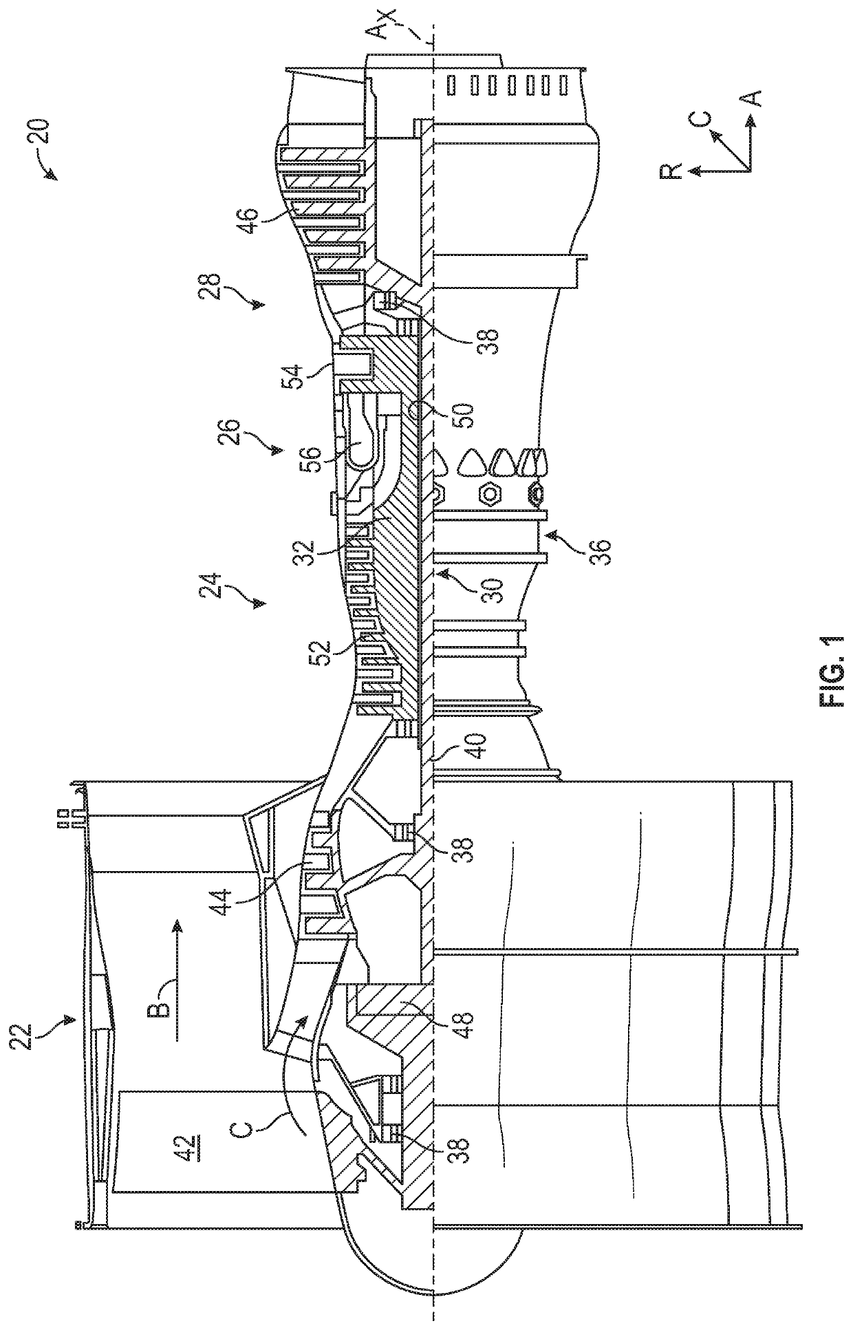
[0036]FIG. 1 schematically illustrates a gas turbine engine 20. The gas turbine engine 20 is disclosed herein as a two-spool turbofan that generally incorporates a fan section 22, a compressor section 24, a combustor section 26 and a turbine section 28. The fan section 22 drives air along a bypass flow path B in a bypass duct, while the compressor section 24 drives air along a core flow path C for compression and communication into the combustor section 26 then expansion through the turbine section 28. With reference to FIG. 1, as used herein, “aft” refers to the direction associated with the tail (e.g., the back end) of an aircraft, or generally, to the direction of exhaust of the gas turbine engine (to the right in FIG. 1). The term “forward” refers to the direction associated with the nose ...


PUM


Abstract

Airfoils for gas turbine engines are described. The airfoils include a leading edge, a trailing edge, a pressure side exterior wall, and a suction side exterior wall. A plurality of cooling passages are formed within the airfoil. A plurality of first interior ribs extend from the pressure side exterior wall to the suction side exterior wall, and a plurality of second interior ribs extend from the suction side exterior wall toward the pressure side exterior wall and intersect with a first interior rib. At least one pressure side main body cooling passage is defined between the pressure side exterior wall and two first interior ribs of the plurality of first interior ribs and at least one suction side main body cooling passage is defined between the suction side exterior wall, a first interior rib, and a second interior rib.

Description

CROSS REFERENCE TO RELATED APPLICATIONS[0001]This application claims the benefit of an earlier filing date from U.S. Provisional Application Ser. No. 62 / 842,656, filed May 3, 2019, the entire disclosure of which is incorporated herein by reference.BACKGROUND[0002]Illustrative embodiments pertain to the art of turbomachinery, and specifically to turbine rotor components.[0003]Gas turbine engines are rotary-type combustion turbine engines built around a power core made up of a compressor, combustor and turbine, arranged in flow series with an upstream inlet and downstream exhaust. The compressor compresses air from the inlet, which is mixed with fuel in the combustor and ignited to generate hot combustion gas. The turbine extracts energy from the expanding combustion gas, and drives the compressor via a common shaft. Energy is delivered in the form of rotational energy in the shaft, reactive thrust from the exhaust, or both.[0004]The individual compressor and turbine sections in each ...

Claims


Application Information

Patent Timeline
Patent Type & Authority Applications(United States)
IPC IPC(8): F01D5/18
CPCF05D2220/323F05D2260/22141F05D2240/126F01D5/186F01D5/187F05D2260/202F05D2240/301F05D2250/11F05D2250/75F05D2260/941Y02T50/60
Inventor SPANGLER, BRANDON W.MONGILLO, JR., DOMINIC J.
Owner RTX CORP
Why Eureka
Try Eureka