Side-emitting light guide and method for the production thereof

a technology of side-emitting light and light guide, which is applied in the direction of optical light guide, instruments, optics, etc., can solve the problems of limited total luminous flux, disturbing the eye, and failure of individual light diodes, and achieve the effect of high luminan

Active Publication Date: 2021-03-04
SCHOTT AG
View PDF2 Cites 0 Cited by
  • Summary
  • Abstract
  • Description
  • Claims
  • Application Information

AI Technical Summary

Benefits of technology

[0009]The soul is preferably markedly thinner than the light guide in order to achieve a high luminance. In particular, in a preferred embodiment, it is provided that the soul has a cross-sectional area, measured in the direction perpendicular to the longitudinal direction of the light guide, that is smaller by at least a factor of 4, preferably by at least a factor of 20, than the cross-sectional area of at least 0.7 mm2 enclosed by the outer contour of the transparent cladding. However, for a soul that is too thin in relation to the thickness of the light guide, the absolute brightness, in turn, declines. Therefore, in accordance with yet another further development, it is favorable when the soul has a cross-sectional area, measured in the direction perpendicular to the longitudinal direction of the light guide, that is smaller by at most a factor of 2500 than the cross-sectional area of the core.

Problems solved by technology

Thus, in the case of such a chain, the large number of components can rapidly result in the failure of individual light diodes, which is perceived immediately as disturbing to the eye.
However, the total luminous flux is limited by the intensity provided by the light emitter.
Even when the light guide shines homogeneously to the eye, there exists a problem in the case of a nonlinear course of the light guide.
If a light guide made of glass is used, it is generally not sufficiently flexible when it has an adequate thickness.
Although light guides made of plastic are known, the known solutions have only a small luminance, however.
In addition, a problem can arise during bending of the light guide.
However, for a soul that is too thin in relation to the thickness of the light guide, the absolute brightness, in turn, declines.
Also the problem that, during bending, detachment can occur between the plastic layers of a plastic light guide, thereby resulting in a local change in the light emission, is circumvented for the light guide described here, in that the light emission from a soul originates in the interior of the core, which is near to or on the neutral fibers.

Method used


Image

  • Side-emitting light guide and method for the production thereof
  • Side-emitting light guide and method for the production thereof
  • Side-emitting light guide and method for the production thereof

Examples


Embodiment Construction

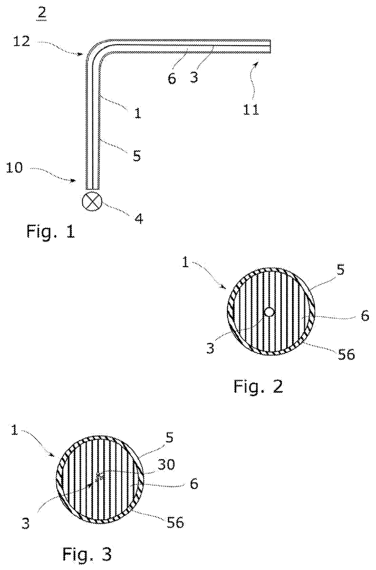
[0021]In FIG. 1, a light source 2 with a light guide 1 in accordance with this disclosure is schematically illustrated. The light source 2 comprises a light emitter 4, which, at one end 10 of the light guide 1, is optically coupled to the core 6 in order to couple light into the light guide 1. In general, without any limitation to the exemplary embodiment illustrated, semiconductor light emitters are preferred for the light source 2, whereby, depending on the field of application, it is also possible, in particular, for lasers of other design constructions, such as, for example, gas lasers, solid-state lasers, excimer lasers, or fiber lasers to find application. They can comprise light-emitting diodes or semiconductor lasers. In this way, it is also possible for a plurality of light emitters of different colors to be coupled in order to obtain an illumination with an adjustable light color. In contrast to what is illustrated in FIG. 1, it is also possible for light emitters 4 to be ...


PUM

PropertyMeasurementUnit
diameteraaaaaaaaaa
areaaaaaaaaaaa
lengthaaaaaaaaaa

Abstract

A light source with a linear appearance is provided. The light source has a flexible light guide that has a homogeneous light emission with high luminance and a emitting light guide. The light emitting guide has a core, in which at least one soul extends, and a transparent cladding that surrounds the core. The core and the cladding are formed from transparent plastic. The core has a higher index of refraction than the cladding. The soul is light-deflecting, light-reflecting, or light-scattering so as to scatter light guided in the light guide and to emit the light through the cladding toward the outside. The soul has a scattering length that is at most twice as large as a maximum cross-sectional dimension of the soul.

Description

CROSS REFERENCE TO RELATED APPLICATIONS[0001]This application claims benefit under 35 USC 119 of German application 10 2019 123 693.2 filed Sep. 4, 2019, the entire contents of which are incorporated herein by reference.BACKGROUND1. Field of the Invention[0002]The invention relates to the technical field of light-emitting elements in general. In particular, the invention relates to the use of light guides in lighting devices or display devices.2. Description of Related Art[0003]For lighting or display purposes, it may be desirable to utilize linear light sources. A light emitter having a side-emitting light guide coupled to it can serve as such a light source. In terms of a space-saving construction and also a high robustness, among other things, such an arrangement is superior to an arrangement composed of many small, adjacently arranged emitters, such as, for instance, an LED chain. Thus, in the case of such a chain, the large number of components can rapidly result in the failure...

Claims


Application Information

Patent Timeline
Patent Type & Authority Applications(United States)
IPC IPC(8): F21V8/00
CPCG02B6/001G02B6/003G02B6/443G02B1/045G02B1/046G02B1/048G02B6/0001
Inventor KAPPEL, MARKUSHOPPE, BERNDRUSSERT, HUBERTUSWILLMES, LOTHAR
Owner SCHOTT AG
Why Eureka
Try Eureka