Removable vise handle

a vise handle and lockable technology, applied in the field of vise handles, can solve the problems of inability to remove, children may use the vise in unsafe manner, and the handle extending into the walkway was likely to cause injury, and achieve the effect of a greater cross-sectional area

Inactive Publication Date: 2007-06-26
RITZ EUGENE A
View PDF15 Cites 2 Cited by
  • Summary
  • Abstract
  • Description
  • Claims
  • Application Information

AI Technical Summary

Benefits of technology

[0009]These needs and others are met by the present invention which provides a vise handle which is both lockable and removable. The removable handle includes a base member, which is fixed to the vise threaded rod, a handle member and a locking assembly. Preferably, the base member is a tubular member with a lateral coupling device. The coupling device is structured to attach the base member to the threaded rod. The tubular member has an inner cross-sectional area and a longitudinal axis. The longitudinal axis extends generally perpendicular to the vise threaded rod. The handle member is an elongated rod having a first end portion, a second end portion and a medial portion. The medial portion has a cross-sectional area that is smaller than the cross-sectional area of the tubular member inner cross-sectional area. In one embodiment, the first and second end portions of the rod have a cross-sectional area that is larger that the cross-sectional area of the tubular member. Hereinafter, where the first and second end portions have a greater cross-sectional area than the tubular member inner diameter, the first and second end portions will be referred to as “wide end portions.” The locking assembly couples the handle member to the base member as described below.

Problems solved by technology

That is, a fixed handle for example, would typically require the user's handle hand to move into an uncomfortable orientation at some point as the handle rotated through 360 degrees.
The disadvantage to the traditional handle is that it cannot be removed.
A handle extending into the walkway was likely to cause injury.
For example, children may use the vise in an unsafe manner.
Further, in a school shop or technology laboratory setting, the rattling of vise handles is a source of annoyance for teachers during lecture or demonstrations.
Such handles are rigid and do not incorporate the sliding action of fixed handles.
Additionally, because such handles are not lockable, the handles may be removed, and even stolen, by unauthorized users.

Method used


Image

  • Removable vise handle
  • Removable vise handle
  • Removable vise handle

Examples


Embodiment Construction

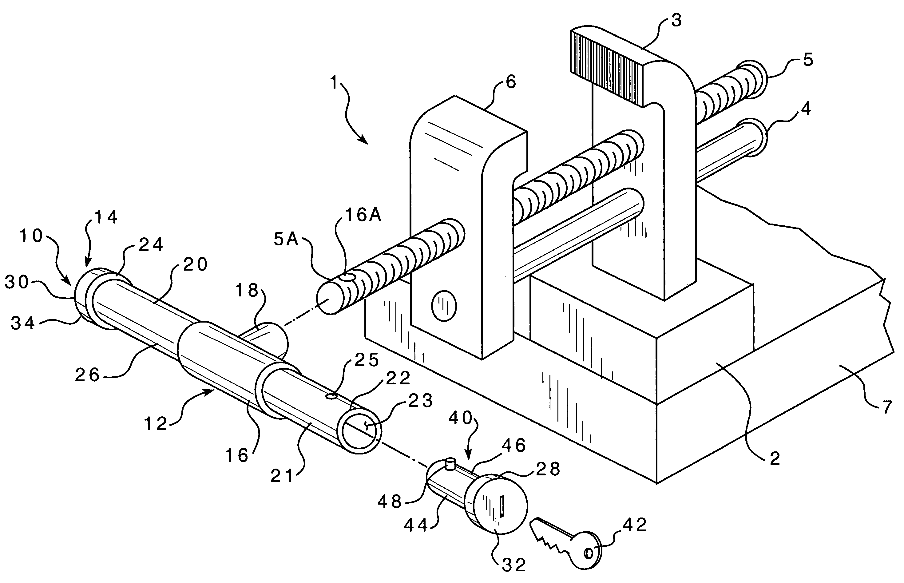
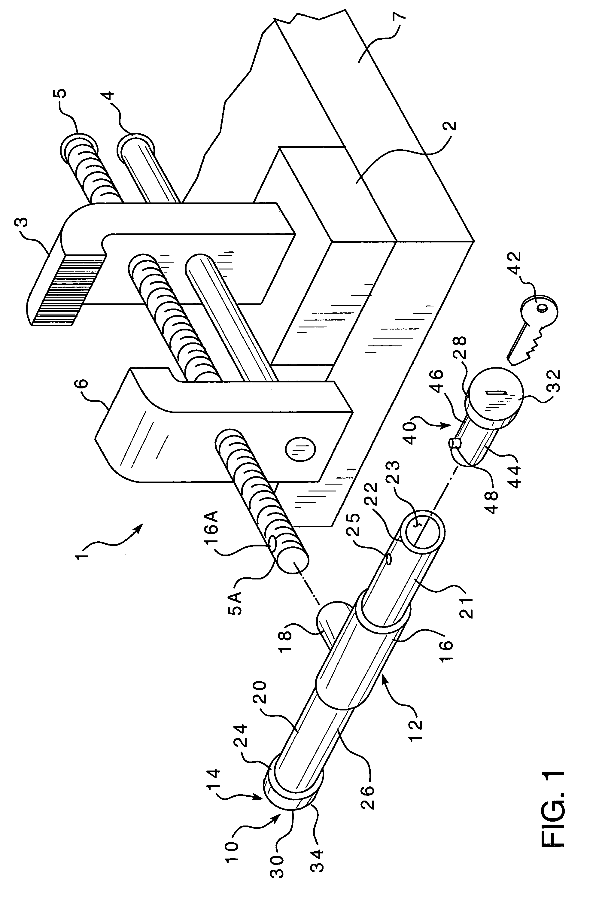
[0016]As shown in FIG. 1, a vise 1 includes a base 2, a fixed jaw 3, a guide rod 4, a threaded rod 5, and a movable jaw 6. The base 2 is typically coupled to the top of, or underneath, a corner of a workbench 7. The fixed jaw 3 is fixed to the base 2. The guide rod 4 extends through, and typically is structured to move through, the fixed jaw 3. The threaded rod 5 extends generally parallel to the guide rod 4. The threaded rod 5 engages a threaded opening (not shown) in the fixed jaw 3. The movable jaw 6 is coupled to the guide rod 4. A first end 5A of the threaded rod 5 extends through, but does not engage, the movable jaw 6. In this configuration, the movable jaw 6 is structured to move toward, or away from, the fixed jaw 3 as the threaded rod 5 is rotated.

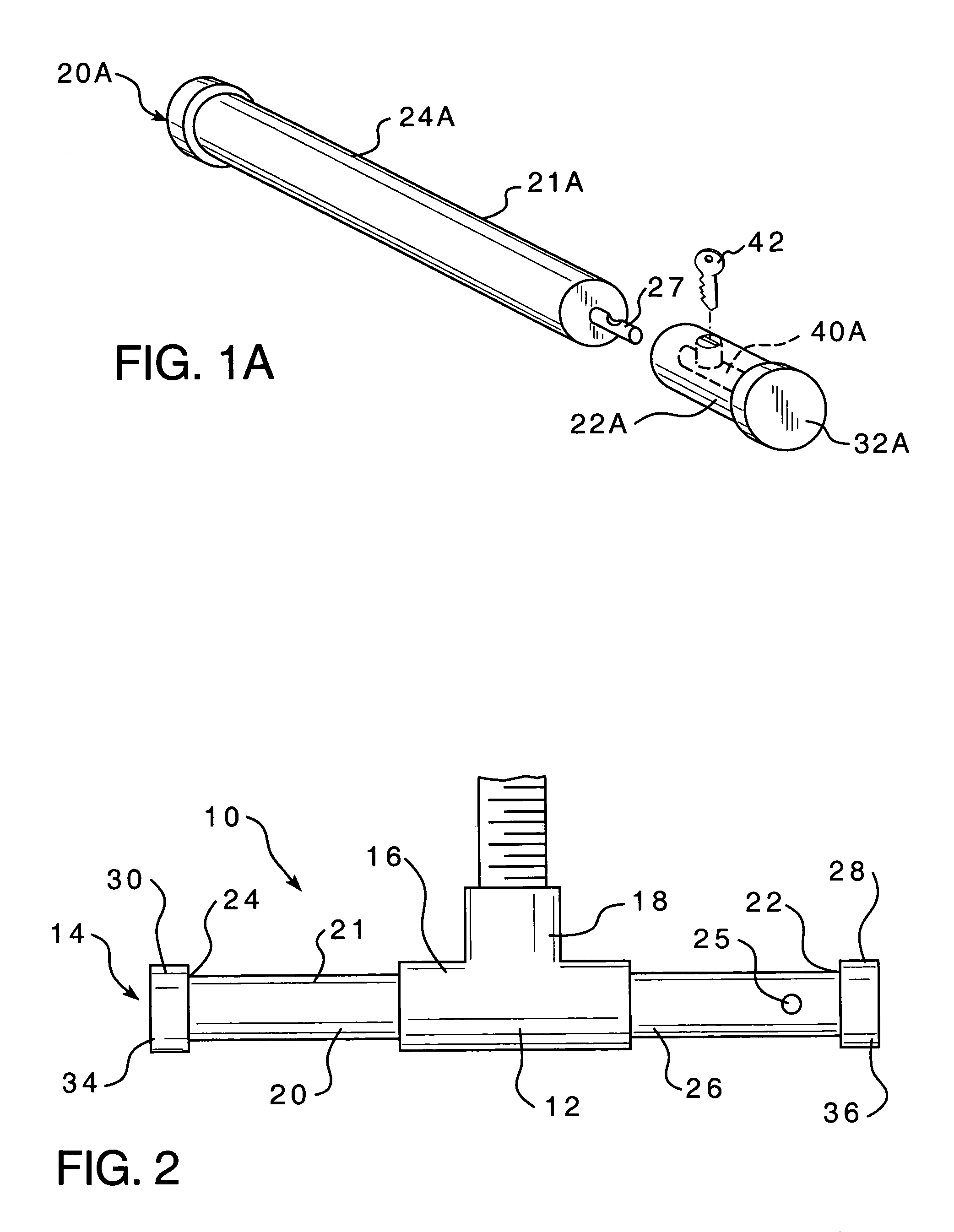
[0017]The threaded rod 5 is rotated by the locking, removable handle assembly 10. The handle assembly 10 includes a base assembly 12, an elongated handle member 14 and a lock assembly 40. The base assembly 12 is structured to be ...


PUM


Abstract

A locking, removable handle assembly for a vise is provided. The vise has a threaded rod, a fixed jaw, and a movable jaw as is known in the art. The handle assembly includes a base assembly, an elongated handle member, and a lock assembly. The base assembly is structured to be fixed to the threaded rod. The elongated handle member is structured to be coupled to the base assembly. The lock assembly is structured to selectively couple the handle member to the base assembly.

Description

BACKGROUND OF THE INVENTION[0001]1. Field of the Invention[0002]This invention relates to a vise handle and, more specifically, to a removable and lockable vise handle.[0003]2. Background Information[0004]A bench vise is a common work shop tool used to secure a workpiece. The vise typically has a fixed jaw and a movable jaw which are coupled together by a threaded rod. The movable jaw is structured to move toward or away from the fixed jaw when the threaded rod is rotated. The threaded rod is typically rotated manually by a handle. The handle typically extends generally perpendicular to the threaded rod. To improve leverage and to make rotating the threaded rod easier, the handle is typically structured to slide relative to the threaded rod. That is, the threaded rod, or an attachment device fixed thereto, includes an opening that extends across the diameter of the rod and the handle, which is an elongated rod having a cross-sectional area that is smaller than the cross-sectional ar...

Claims


Application Information

Patent Timeline
Patent Type & Authority Patents(United States)
IPC IPC(8): G05G1/10
CPCB25B1/103B25B1/24G05G5/28G05G1/06Y10T74/20732Y10T70/5832Y10T70/411
Inventor RITZ, EUGENE A.
Owner RITZ EUGENE A
Why Eureka
Try Eureka