Eureka AIR delivers breakthrough ideas for toughest innovation challenges, trusted by R&D personnel around the world.

Measurement system

Inactive Publication Date: 2019-10-17
FROST CONTROL SYST INC
View PDF0 Cites 3 Cited by
  • Summary
  • Abstract
  • Description
  • Claims
  • Application Information

AI Technical Summary

Benefits of technology

The present disclosure describes various embodiments of a measurement system that includes an enclosure with an opening and a male insert that is coupled to the enclosure. The male insert has a stem and a central opening. The measurement system also includes a female insert or a compression nut that is detachably coupled to the male insert. The opto-electronic sensor is housed inside the central opening along the stem of the male insert. The measurement system provides a substantially unobstructed viewport for the opto-electronic sensor. The technical effects of the invention include improved optical sensor performance, reduced interference with the measurement system, and improved user experience.

Problems solved by technology

However, electromagnetic radiation cannot normally pass through glass.
Such crystal lenses are costly, reduce the quality of the temperature measurement by the infrared sensor, and require maintenance to keep the lens free of obstructions, such as dirt, moisture, and ice.
This process is timely and costly because infrared temperature sensors for road temperature monitoring are typically installed on traffic signal mast arms 25 feet above busy intersections and require multiple hours of labor (e.g., electrical work) to install.
These estimates are inaccurate, however, due to exterior influences on the enclosure, such as ambient exterior air temperature.
Moreover, related art temperature measurement systems utilize fans to distribute heat generated by the device to mitigate temperature differentials within the device, which might otherwise cause temperature measurement inaccuracies.
However, fans are prone to costly failure due to their mechanical nature, require significant power consumption, and are an expensive component.

Method used


Image

  • Measurement system
  • Measurement system
  • Measurement system

Examples


Embodiment Construction

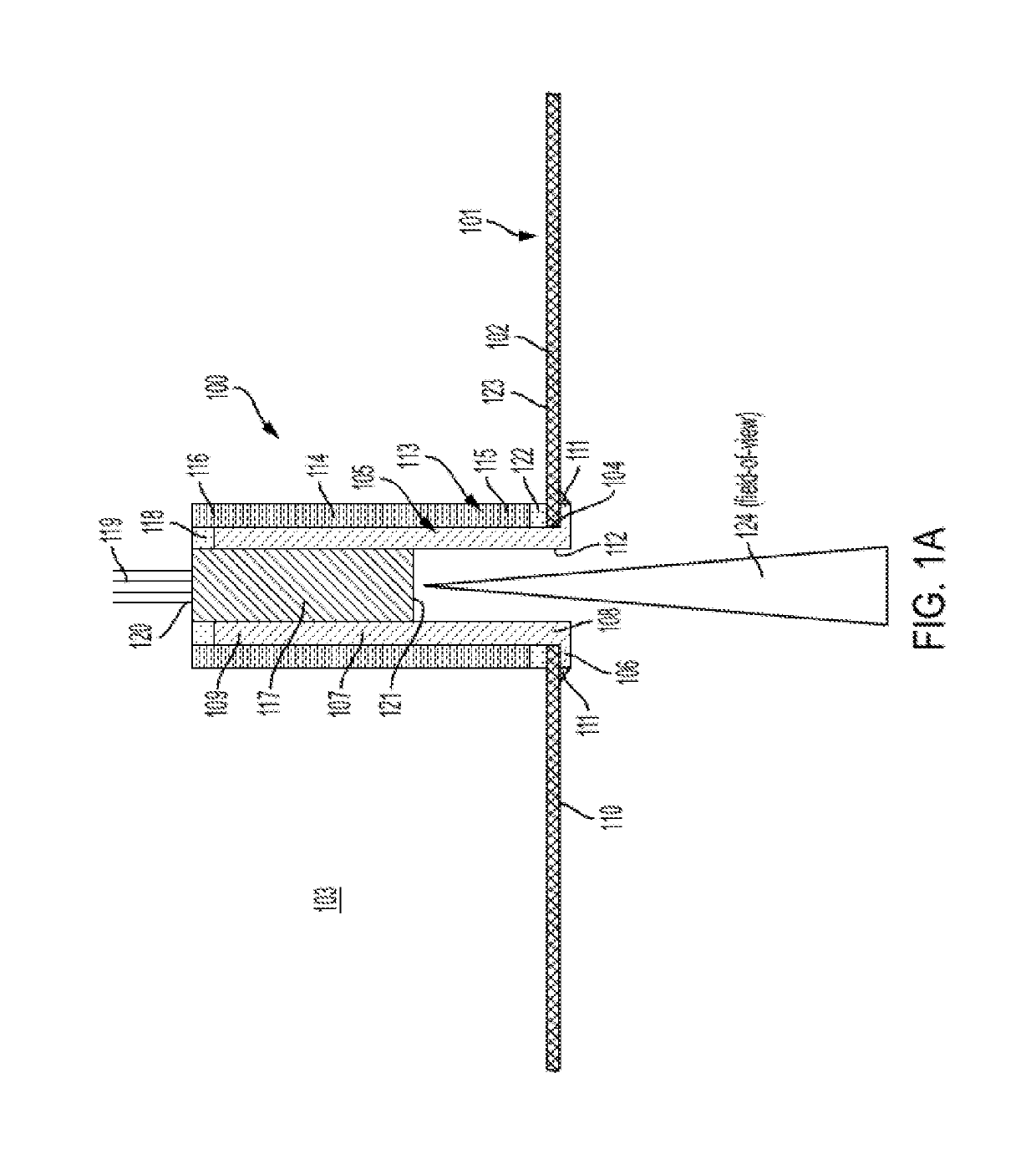
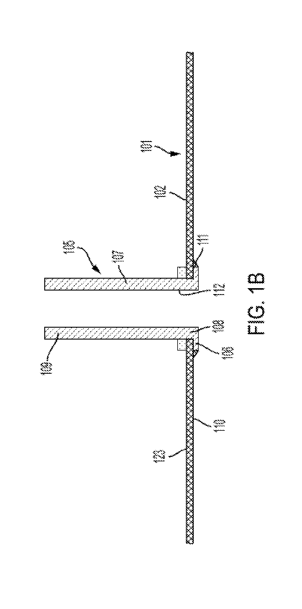
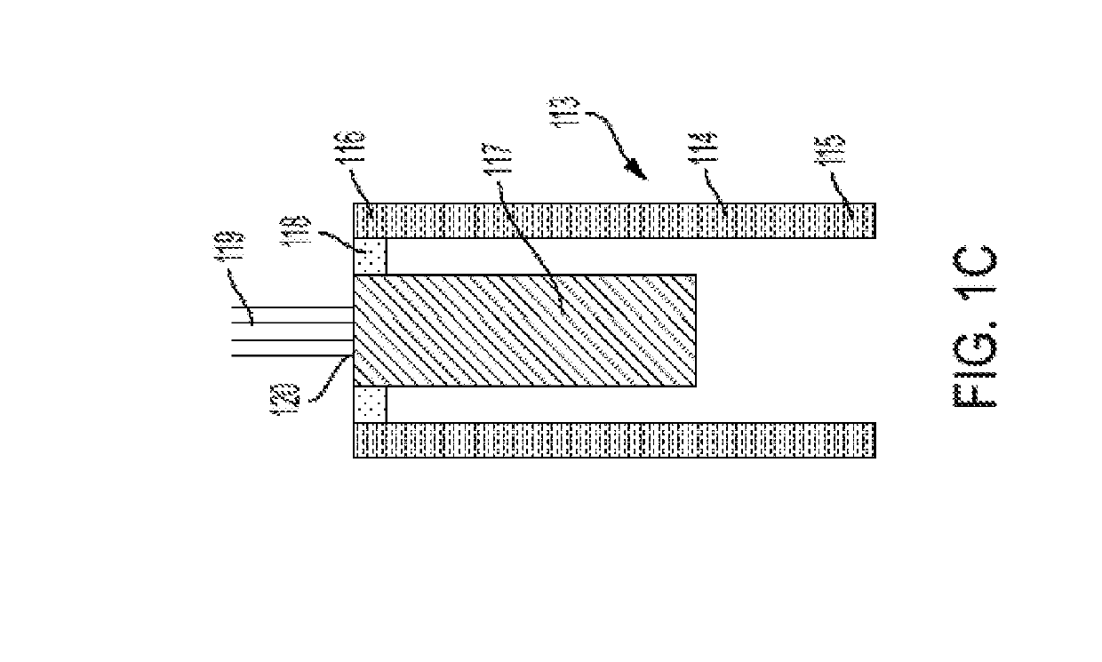
[0034]The present disclosure is directed to various embodiments of a measurement system. In one or more embodiments, the measurement system is a temperature measurement system configured to perform road temperature measurements. Road temperature measurements are utilized in the winter road maintenance industry to determine, for instance, the type and / or quantity of deicer material to place on the road. In one or more embodiments, the temperature measurement system of the present disclosure is configured to enable convenient and cost-effective servicing of the temperature sensor and eliminates the need for costly crystal viewport lenses. Additionally, in one or more embodiments, the measurement system (e.g., the temperature measurement system) of the present disclosure is provided without a fan for evenly distributing heat within an enclosure of the system, which makes the measurement systems of the present disclosure less prone to failure and less costly to manufacture and operate t...


PUM


Abstract

A measurement system includes an enclosure having at least one sidewall defining an interior space and at least one opening in the at least one sidewall, and a male insert configured to be coupled to the at least one sidewall of the enclosure. The male insert includes a flange configured to engage an exterior surface of the at least one sidewall around the opening, a stem configured to extend through the opening and into the interior space, and a central opening. The measurement system also includes a female insert configured to be detachably coupled to the male insert inside the interior space, and an opto-electronic sensor configured to be housed inside central opening along the stem of the male insert. The measurement system defines a substantially unobstructed viewport for the opto-electronic sensor.

Description

CROSS-REFERENCE TO RELATED APPLICATION[0001]This application claims priority to and the benefit of U.S. Provisional Application No. 62 / 656,877, filed Apr. 12, 2018, the entire contents of which are incorporated herein by reference.BACKGROUND1. Field[0002]The present disclosure relates generally to measurement systems.2. Description of the Related Art[0003]Sensors placed outdoors, such as infrared temperature sensors, often require watertight enclosures to protect the sensor and / or the associated circuitry. Infrared temperature sensors are utilized in the winter road maintenance industry to measure road temperature. The measured temperature of the road may be utilized to determine the type and quantity of deicer material to place on the road. Infrared temperature sensors determine the road temperature by measuring the electromagnetic radiation emanating from the road.[0004]In some related art temperature measurement systems including an infrared sensor, the infrared sensor is housed ...

Claims


Application Information

Patent Timeline
IPC IPC(8): G01D11/24
CPCG01D11/245G01J1/0271G01J1/0403G01J5/04G01J5/041G01J5/045G01J5/046G01J2001/0276G01J2001/028G01J5/05G01J5/064
Inventor TENER, BRADLEY JAMES
Owner FROST CONTROL SYST INC
Why Eureka
Eureka Blog
Learn More