
Techniques for bounding cleaning operations of a robotic surface cleaning device within a region of interest

a robotic surface cleaning and region of interest technology, applied in the direction of cleaning action control, process and machine control, instruments, etc., can solve the problems of physical fatigue, lack of ability to adapt to cleaning requirements, and robotic vacuums tend to operate autonomously

Active Publication Date: 2019-10-24
SHARKNINJA OPERATING LLC
View PDF0 Cites 10 Cited by
  • Summary
  • Abstract
  • Description
  • Claims
  • Application Information

AI Technical Summary

Benefits of technology

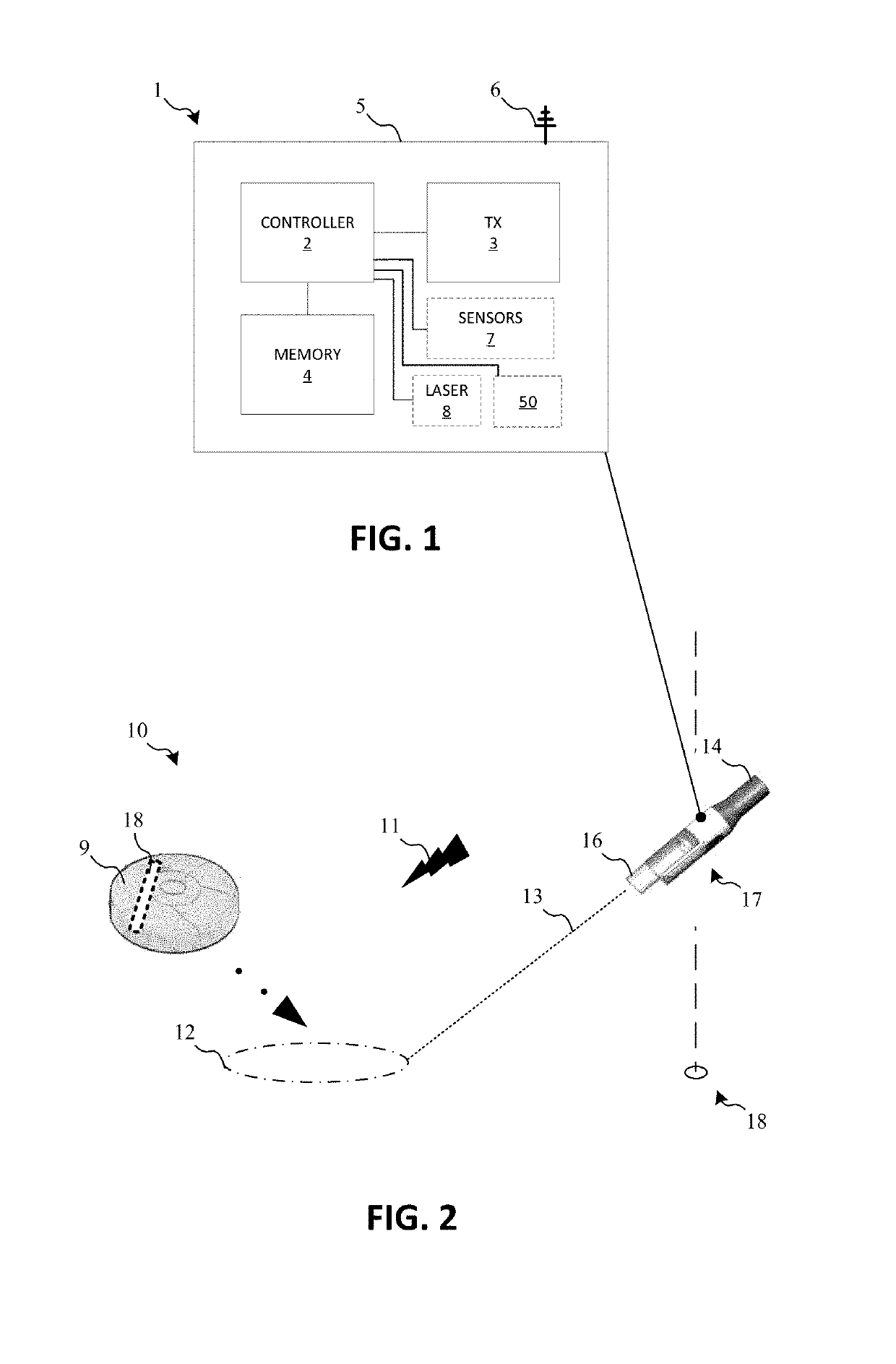
The present patent is about a hand-held surface cleaning device that can communicate with a robotic vacuum or surface cleaning device to target specific areas for cleaning. This device includes circuitry to communicate with the robotic device and a camera to extract three-dimensional information from the environment. This information can be used to map the location of walls, stairs, obstacles, and other features in a given area. The robotic device can then use this mapping information in real-time control to direct its cleaning efforts. The patent is not limited to using computer vision systems in the hand-held and robotic devices.

Problems solved by technology

Even when a vacuum is self-propelled, e.g., by a drive motor, extended use of such vacuums can result in physical fatigue.
However, robotic vacuums tend to operate autonomously and lack the ability to adapt to cleaning requirements that change on-the-fly.
For example, a robotic vacuum may be unaware an accidental spill has occurred across the room and may take a significant amount of time before the robotic vacuum naturally arrives at the mess.

Method used


Image

  • Techniques for bounding cleaning operations of a robotic surface cleaning device within a region of interest
  • Techniques for bounding cleaning operations of a robotic surface cleaning device within a region of interest
  • Techniques for bounding cleaning operations of a robotic surface cleaning device within a region of interest

Examples


Embodiment Construction

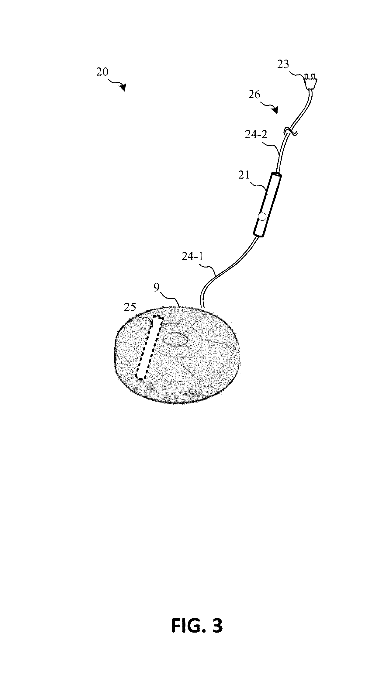
[0015]In general, the present disclosure is directed to a hand-held surface cleaning device that includes circuitry to communicate with a robotic surface cleaning device to cause the same to target an area / region of interest for cleaning. Thus, a user may utilize the hand-held surface cleaning device to perform targeted cleaning (e.g., so-called “spot” cleaning) and conveniently direct a robotic surface cleaning device to focus on a region of interest. Moreover, the hand-held surface cleaning device may include sensory such as a camera device (or other suitable vision system) for extracting three-dimensional information from a field of view. This information may be utilized to map locations of walls, stairs, obstacles (e.g., furniture, toys, and so on), changes in surface types (e.g., wood floors versus carpet), and other features in a given location. Thus, a robotic surface cleaning device may utilize the mapping information from the hand-held surface cleaning device as an input in...


PUM


Abstract

In general, the present disclosure is directed to a hand-held surface cleaning device that includes circuitry to communicate with a robotic surface cleaning device to cause the same to target an area / region of interest for cleaning. Thus, a user may utilize the hand-held surface cleaning device to perform targeted cleaning and conveniently direct a robotic surface cleaning device to focus on a region of interest. Moreover, the hand-held surface cleaning device may include sensory such as a camera device for extracting three-dimensional information from a field of view. This information may be utilized to map locations of walls, stairs, obstacles, changes in surface types, and other features in a given location. Thus, a robotic surface cleaning device may utilize the mapping information from the hand-held surface cleaning device as an input in a real-time control loop, e.g., as an input to a Simultaneous Localization and Mapping (SLAM) routine.

Description

CROSS REFERENCE TO RELATED APPLICATIONS[0001]The present application claims the benefit of U.S. Provisional Patent Application Ser. No. 62 / 661,496 filed on Apr. 23, 2018, which is fully incorporated herein by reference.TECHNICAL FIELD[0002]This specification relates to surface cleaning apparatuses, and more particularly, to a hand-held surface cleaning device with a controller arrangement to communicate with a robotic vacuum or robotic surface cleaning device.BACKGROUND INFORMATION[0003]Powered devices, such as vacuum cleaners, have multiple components that each receive electrical power from one or more power sources (e.g., one or more batteries or electrical mains). For example, a vacuum cleaner may include a suction motor to generate a vacuum within a cleaning head. The generated vacuum collects debris from a surface to be cleaned and deposits the debris, for example, in a debris collector. The vacuum may also include a motor to rotate a brush roll within the cleaning head. The ro...

Claims


Application Information

Patent Timeline
Patent Type & Authority Applications(United States)
IPC IPC(8): A47L9/28A47L5/24B25J9/16B25J11/00
CPCA47L9/2826A47L9/2894A47L5/24B25J9/1666A47L2201/06A47L2201/04A47L9/2852B25J11/0085G05D1/0016G05D1/0033G05D1/0274A47L2201/022G05D1/0276
Inventor THORNE, JASON B.BROWN, ANDRE D.CLARE, DAVID S.SARDAR, NICHOLASPINCHES, CHRISTOPHER P.JAMES, SAMUEL EMRYSDOUGLAS, MICHAEL JAMESCROGGON, HUGH J.
Owner SHARKNINJA OPERATING LLC
Learn More