Actuator device and method

a technology of actuators and actuators, applied in the direction of piezoelectric/electrostrictive device details, device material selection, device details, etc., can solve the problem of limited actuation motion and force achievable with such devices, and achieve the effect of imposing the overall deformation pattern

Active Publication Date: 2019-10-24
KONINKLJIJKE PHILIPS NV
View PDF0 Cites 9 Cited by
  • Summary
  • Abstract
  • Description
  • Claims
  • Application Information

AI Technical Summary

Benefits of technology

[0150]This may enable more subtle or intricate sensing capability, wherein changes in shape (e.g. thickness) of different sections of the actuator member may be independently measured. This may for example be particularly advantageous in cases where the actuator member is adapted to be deformable in accordance with non-uniform deformation patterns. In these cases, ...

Problems solved by technology

The range of actuation motions and forces achiev...

Method used


Image

  • Actuator device and method
  • Actuator device and method
  • Actuator device and method

Examples


Embodiment Construction

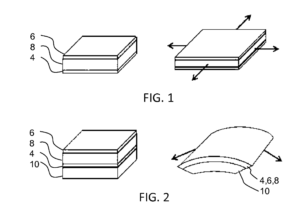
[0176]The invention relates generally to electroactive material actuators comprising for example an electroactive polymer, having embedded magnetic particles for facilitating enhanced actuation and / or sensing effects.

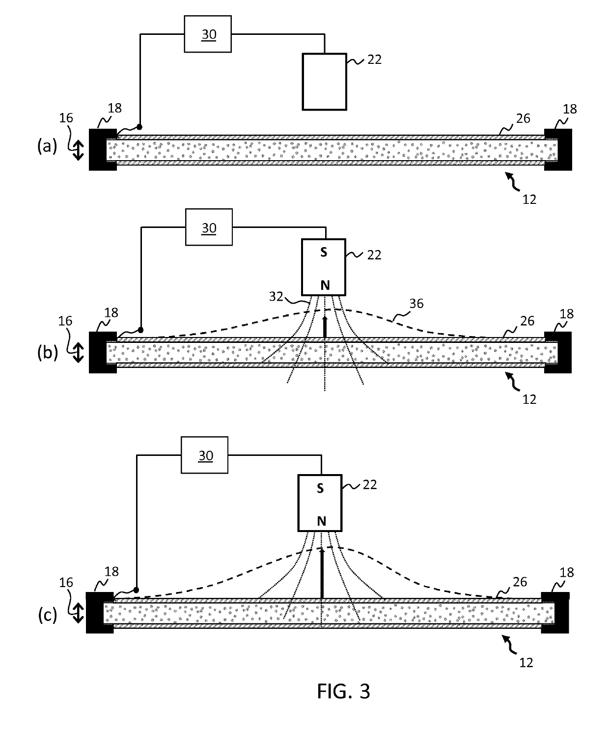
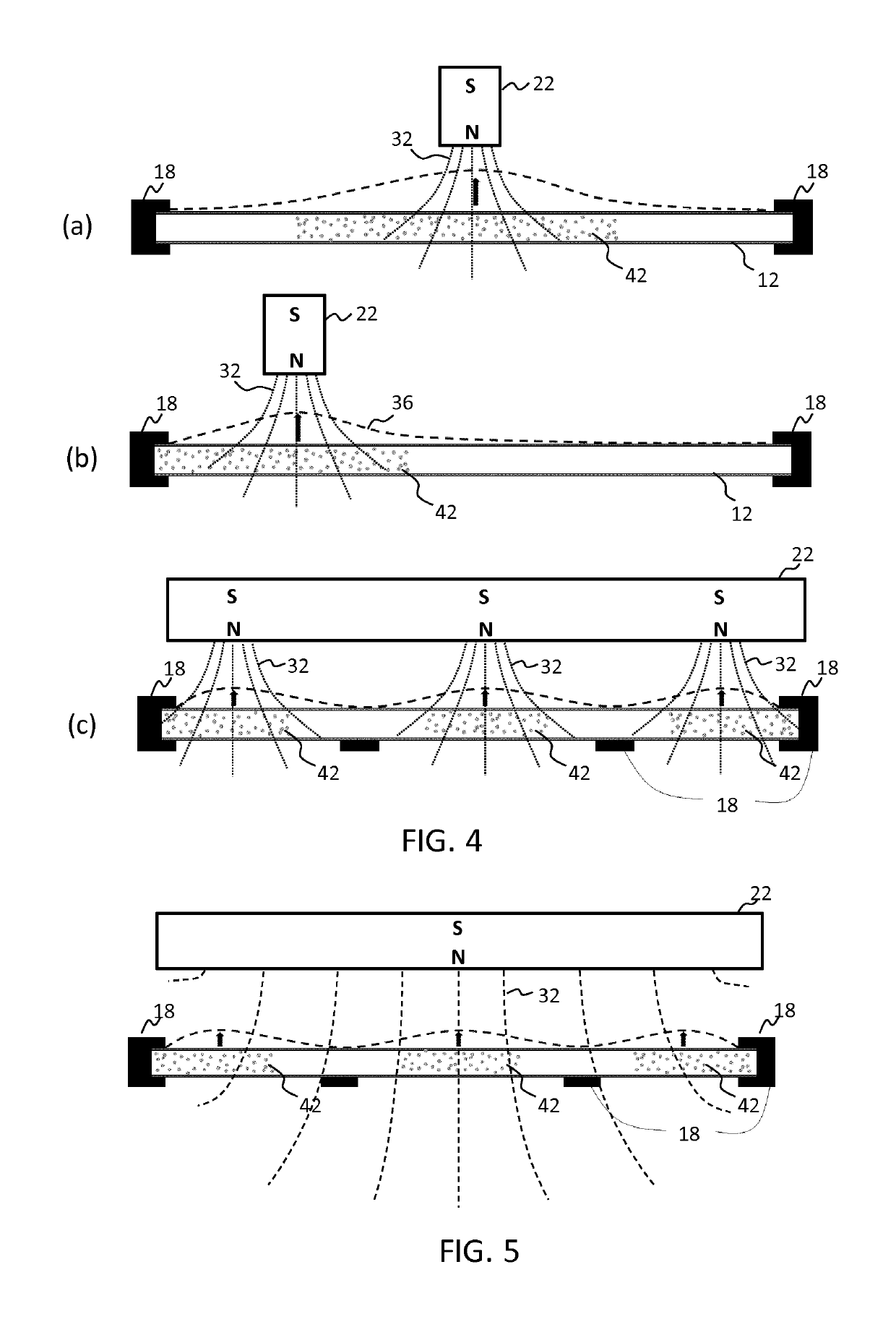
[0177]Examples provide an actuator device including an EAM actuator member having embedded soft magnetic particles and further including means for applying an electrical stimulus and a magnetic field to the actuator member. A controller is adapted to control these two means in a coordinated manner to thereby realize one or more deformation patterns in the actuator member.

[0178]Examples provide an actuator device including an EAM actuator member having embedded hard magnetic particles and further including means for applying an electrical stimulus and a magnetic field to the actuator member. A controller is adapted to control these two means in a coordinated manner to thereby realize a one or more deformation patterns in the actuator member.

[0179]Examples provide an ac...


PUM


Abstract

The invention relates generally to electroactive material actuators (and combined sensor-actuators) having embedded magnetic particles (42) for facilitating enhanced actuation and/or sensing effects.

Description

FIELD OF THE INVENTION[0001]This invention relates to an actuator device, in particular an actuator device comprising an electroactive material.BACKGROUND OF THE INVENTION[0002]Electroactive materials (EAMs), and in particular electroactive polymers (EAPs) are an emerging class of materials within the field of electrically responsive materials. EAPs can work as sensors or actuators and can easily be manufactured into various shapes allowing easy integration into a large variety of systems.[0003]Materials have been developed with characteristics such as actuation stress and strain which have improved significantly over the last ten years. Technology risks have been reduced to acceptable levels for product development so that EAPs are commercially and technically becoming of increasing interest. Advantages of EAPs include low power, small form factor, flexibility, noiseless operation, accuracy, the possibility of high resolution, fast response times, and cyclic actuation.[0004]The imp...

Claims


Application Information

Patent Timeline
IPC IPC(8): H01L41/18H01L41/04H01L41/09H01L41/083H01L41/113H01L41/193H01L41/20H01L41/06H01L41/12
CPCH01L41/0986H01L41/042H01L41/183H01L41/125H01L41/193H01L41/0926H01L41/083H01L41/20H01L41/06H01L41/1132H10N30/802H10N30/204H10N30/206H10N30/85H10N30/852H10N30/50H10N30/302H10N30/857H10N35/80H10N35/85H10N35/101
Inventor PELSSERS, EDUARD GERARD MARIEVAN DEN ENDE, DAAN ANTONJOHNSON, MARK THOMASHENDRIKS, CORNELIS PETRUS
Owner KONINKLJIJKE PHILIPS NV
Why Eureka
Try Eureka