Check patentability & draft patents in minutes with Patsnap Eureka AI!

Additive manufacturing system with moveable sensors

Inactive Publication Date: 2019-10-31
HAMILTON SUNDSTRAND CORP
View PDF1 Cites 6 Cited by
  • Summary
  • Abstract
  • Description
  • Claims
  • Application Information

AI Technical Summary

Benefits of technology

The patent is for an additive manufacturing system that uses an energy gun to melt a raw material layer and create a solid slice of a workpiece. The system includes a sensor that can detect surface and sub-surface anomalies or physical properties of the workpiece. The sensor can be an x-ray sensor, ultrasonic sensor, thermal sensor, and so on. The positioning mechanism can move the sensor in both a normal direction and a parallel direction relative to the workpiece's surface. The system can create multiple slices on top of each other and detect if the anomalies are still present. The technical effects of this system include improved accuracy and efficiency in detecting and addressing surface and sub-surface anomalies in additive manufacturing processes.

Problems solved by technology

Unfortunately, known additive manufacturing processes and systems may produce defects that can jam or stop a manufacturing process and / or are not easily fixed or identifiable after the additive manufacturing process is completed.

Method used


Image

  • Additive manufacturing system with moveable sensors
  • Additive manufacturing system with moveable sensors
  • Additive manufacturing system with moveable sensors

Examples


Embodiment Construction

[0024]A detailed description of one or more embodiments of the disclosed apparatus and method are presented herein by way of exemplification and not limitation with reference to the Figures.

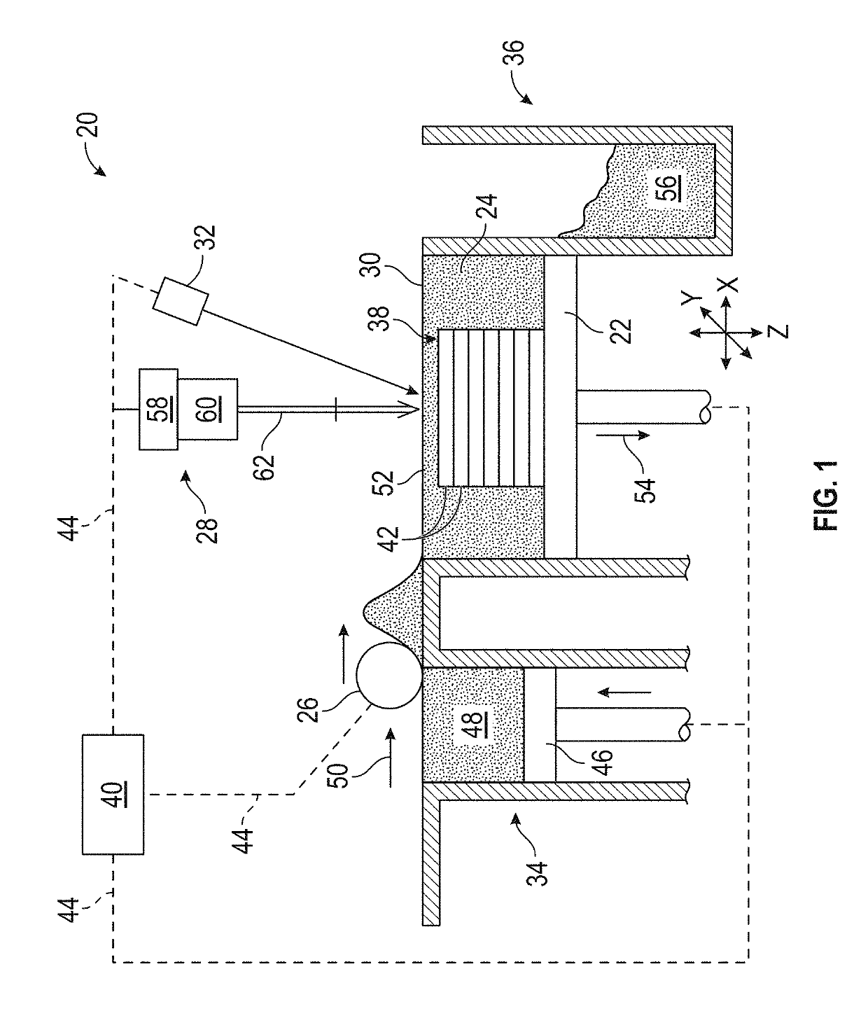
[0025]FIG. 1 schematically illustrates a prior art additive manufacturing system 20 having a build table 22 for holding a powder bed 24, a recoating mechanism such as a particle spreader or wiper 26 for producing the powder bed 24, an energy gun 28 for selectively melting regions of a layer 30 of the powder bed, a surface monitor 32, a powder supply hopper 34 and a powder surplus hopper 36. The additive manufacturing system 20 is constructed to build a workpiece 38 in a layer-by-layer fashion utilizing an additive manufacturing process controlled by an electrical controller 40 that may have an integral computer aided design system for modeling the workpiece 38 into a plurality of slices 42 additively built atop one-another generally in a vertical or z-coordinate direction.

[0026]The controller 40 ...


PUM

PropertyMeasurementUnit
Energyaaaaaaaaaa
Physical propertiesaaaaaaaaaa

Abstract

An additive manufacturing system includes an energy gun for melting at least a portion of a raw material layer and thereby forming at least in part a slice of a workpiece and a sensor for detecting surface and sub-surface anomalies or physical properties of the portion. The system also includes a positioning mechanism that moves the sensor in at least one of a normal direction and a parallel direction relative to an upper surface of the workpiece.

Description

BACKGROUND[0001]Exemplary embodiments pertain to the art of additive manufacturing system and, more particularly, to an additive manufacturing system with subsurface inspection capabilities.[0002]Traditional additive manufacturing systems include, for example. Additive Layer Manufacturing (ALM) devices, such as Direct Metal Laser Sintering (DMLS). Selective Laser Melting (SLM), Laser Beam Melting (LBM) and Electron Beam Melting (EBM) that provide for the fabrication of complex metal, alloy, polymer, ceramic and composite structures by the freeform construction of the workpiece, layer-by-layer. The principle behind additive manufacturing processes involves the selective melting of atomized precursor powder beds by a directed energy source, producing the lithographic build-up of the workpiece. The melting of the powder occurs in a small localized region of the energy beam, producing small volumes of melting, called melt pools, followed by rapid solidification, allowing for very precis...

Claims


Application Information

Patent Timeline
IPC IPC(8): B23K26/342B23K26/03B23K26/06B23K26/082
CPCB33Y30/00B33Y10/00B23K26/034B23K26/082B23K26/0648B23K26/0643B23K26/0342B33Y50/02B23K26/032B23K26/342B29C64/153B29C64/232B29C64/236B29C64/30B33Y40/00B29C64/393Y02P10/25B22F12/222B22F12/224B22F10/31B22F10/38B22F10/28B22F12/41B22F12/90
Inventor DEFORGE, JASENREYNOLDS, SHAWN KARLMUGRAGE, ANDY
Owner HAMILTON SUNDSTRAND CORP
Features
  • R&D
  • Intellectual Property
  • Life Sciences
  • Materials
  • Tech Scout
  • Unparalleled Data Quality
  • Higher Quality Content
  • 60% Fewer Hallucinations
Learn More