Parallel link device, industrial robot, and haptic presentation device

a technology of parallel-serial composite structure and haptic display, which is applied in the direction of mechanical control device, program-controlled manipulator, medical science, etc., can solve the problem that all of the force of six motors cannot be used as a driving force at a distal end side, and the inertia at the distal end side of such a parallel-serial composite structure may easily become relatively larg

Active Publication Date: 2019-10-31
SONY CORP
View PDF0 Cites 3 Cited by
  • Summary
  • Abstract
  • Description
  • Claims
  • Application Information

AI Technical Summary

Benefits of technology

[0015]As described above, according to this disclosure, translational motions with three degrees of freedom and rotational motions with three degrees of freedom of a movable member of a parallel link device can be performed in a wide range of motion.
[0016]Note that the effects described above are not necessarily limitative. With or in the place of the above effects, there may be achieved any one of the effects described in this specification or other effects that may be grasped from this specification.

Problems solved by technology

Furthermore, parallel link robots also have characteristics that, since actuators such as motors can be disposed at a base side instead of distal end sides of arm parts; it is difficult for the weight of the actuators themselves to cause a large load on outputs of the actuators.
However, in such a parallel link device, a translational motion of a movable member is produced through a parallel link structure, a rotational motion is realized in a serial structure, and thus all of the force of six motors cannot be used as a driving force at a distal end side.
Furthermore, it can be said that the inertia at the distal end side of such a parallel-serial composite structure may easily become relatively large.

Method used


Image

  • Parallel link device, industrial robot, and haptic presentation device
  • Parallel link device, industrial robot, and haptic presentation device
  • Parallel link device, industrial robot, and haptic presentation device

Examples


second embodiment

2. Second Embodiment

[0145]Next, a parallel link device according to a second embodiment of this disclosure will be described. In the parallel link device related to this embodiment, coupling parts between a plurality of arm parts and a base part are unevenly located around a rotational central point P in a predetermined range. Similarly, in the parallel link device, coupling parts between the plurality of arm parts and a movable member are unevenly located around a rotational central point Q in a predetermined range. Hereinafter, differences between the parallel link device related to this embodiment and the parallel link device related to the first embodiment will be mainly described.

[0146]FIG. 16 is an explanatory diagram illustrating a structure of a parallel link device 210 related to this embodiment. In the parallel link device 210 related to this embodiment, fixed parts 231a, 231b, and 231c which are provided on a base plate 230 serving as a base part and to which a first arm ...


PUM


Abstract

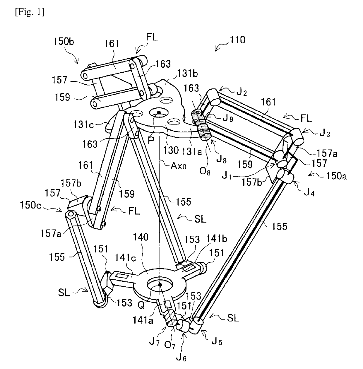
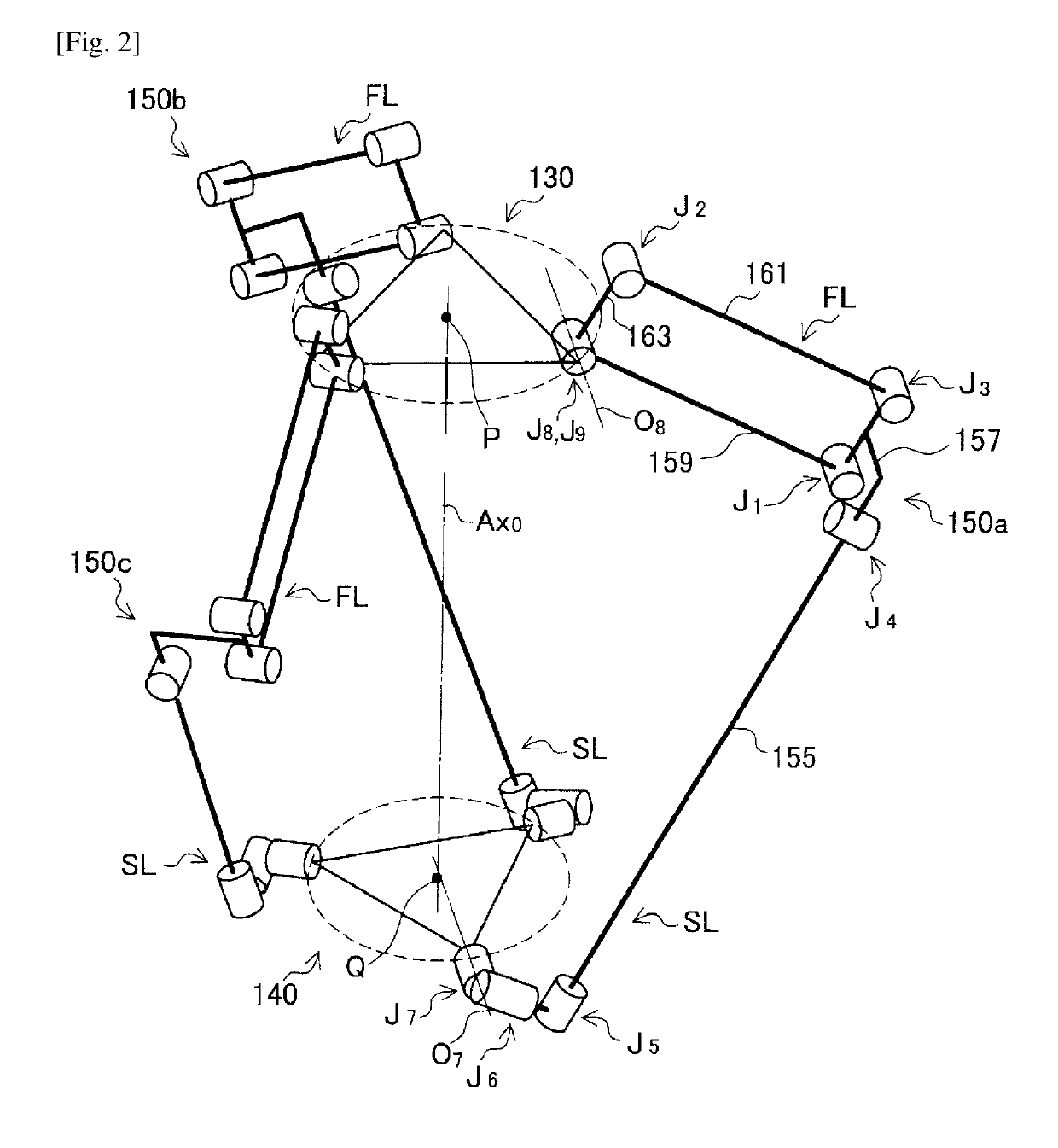
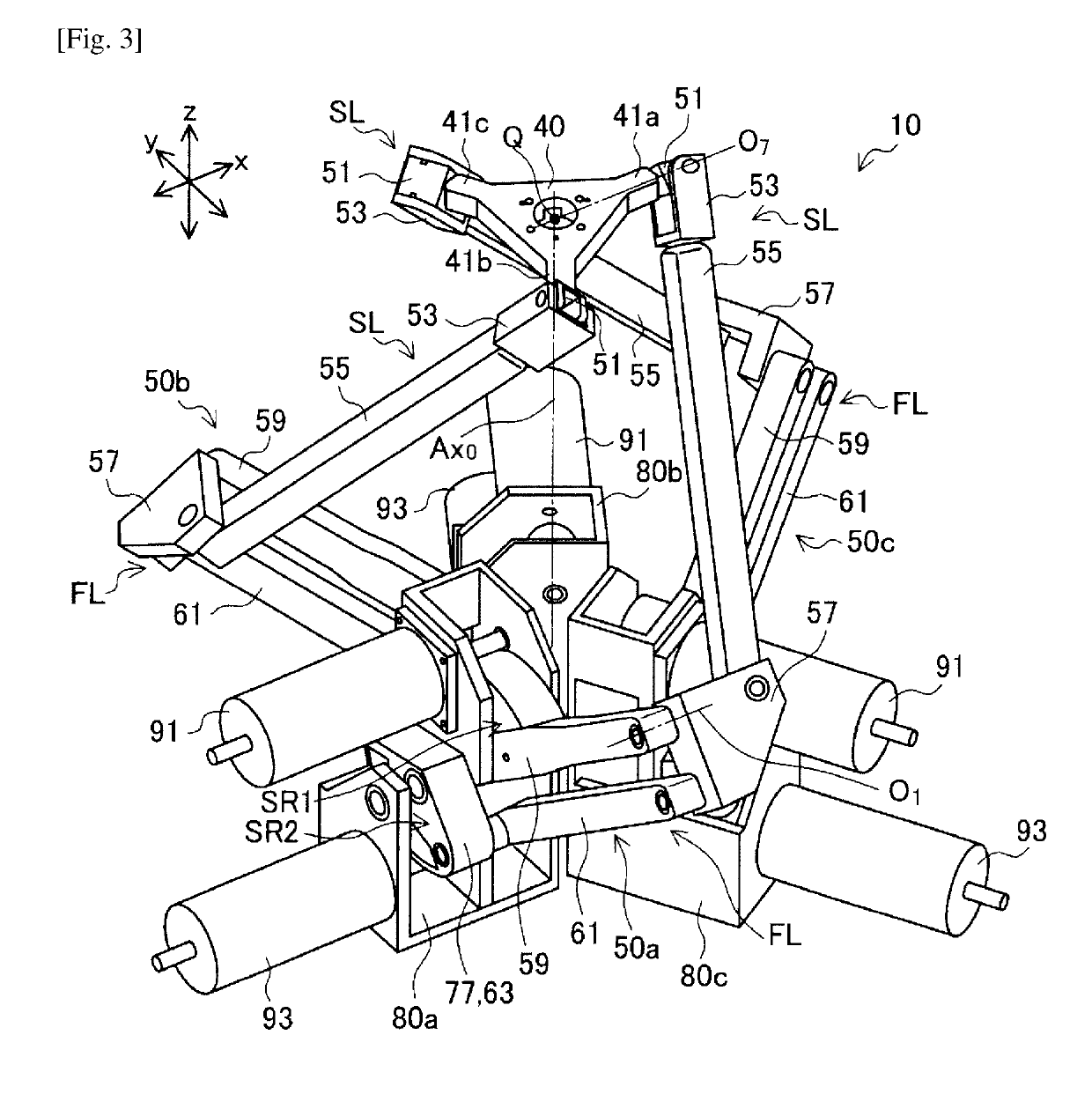
There is provided a parallel link device including a base, a plurality of arms each having at least four degrees of freedom and each including a first arm link, a second arm link, and a rotating joint, and a support which is coupled to an end of the second arm link of each of the plurality of the arms, and a position and a posture of which changes along with changes of posture of the plurality of the arms, where an axis of rotation (O7) of the rotating joint, which is coupled to the support and the second arm link, intersects or is adjacent to a rotational central point (Q) of the support.

Description

CROSS REFERENCE TO RELATED APPLICATIONS[0001]This application claims the benefit of Japanese Priority Patent Application JP 2016-135809 filed Jul. 8, 2016, the entire contents of which are incorporated herein by reference.TECHNICAL FIELD[0002]This disclosure relates to a parallel link device, an industrial robot, and a haptic presentation device.BACKGROUND ART[0003]In recent years, robots in which parallel links are adopted have received attention as industrial robots. Such parallel link robots have characteristics that distal end sides of a plurality of arm parts constituting parallel links can be constituted to be relatively light and can be produced at relatively low cost. Furthermore, parallel link robots also have characteristics that, since actuators such as motors can be disposed at a base side instead of distal end sides of arm parts; it is difficult for the weight of the actuators themselves to cause a large load on outputs of the actuators. In addition, since distal end si...

Claims


Application Information

Patent Timeline
Patent Type & Authority Applications(United States)
IPC IPC(8): B25J13/02B25J9/16B25J9/06B25J9/00
CPCB25J9/0045B25J9/06B25J13/025B25J9/1623B25J9/0051B25J9/1065B25J13/02A61B2034/742G05G1/01G05G1/015
Inventor HONGO, KAZUO
Owner SONY CORP
Why Eureka
Try Eureka