Wiper device

a technology of a wand and a wand body, which is applied in the direction of vehicle maintenance, vehicle cleaning, transportation and packaging, etc., can solve the problems of erratic wand operation, and achieve the effect of suppressing pressure changes in the interior space and preventing damage to the protective member

Inactive Publication Date: 2019-10-31
DENSO CORP
View PDF0 Cites 2 Cited by
  • Summary
  • Abstract
  • Description
  • Claims
  • Application Information

AI Technical Summary

Benefits of technology

[0011]In the wiper device of the first aspect, the acceleration sensor is installed in the recess inside the wiper arm, and juddering of the wiper blade is suppressed by generating a voltage to reduce the change in acceleration of the wiper arm, detected by the acceleration sensor, and applying this voltage to the wiper motor. The recess inside the wiper arm is isolated from the exterior, and is located at a position enabling easy detection of the change in acceleration of the wiper arm due to vibration of the wiper arm. The acceleration sensor can therefore be installed at an optimal position for suppressing vibration.
[0027]In the wiper device of the ninth aspect, the connector disposed at an end of the signal wire and the protective member is provided with the air hole that is in communication with the interior space of the protective member. This suppresses pressure changes in the interior space within the protective member due to folding and extension of the protective member or due to changes in temperature, thereby preventing the protective member from being damaged as a result of pressure changes in the interior space.

Problems solved by technology

However, with such trial and error it takes time and effort to produce the desired results, and when the voltage applied to the wiper motor is raised, the wiping operation becomes erratic, and issues arise such as the wiper blade overrunning a return position.

Method used


Image

  • Wiper device
  • Wiper device
  • Wiper device

Examples


Embodiment Construction

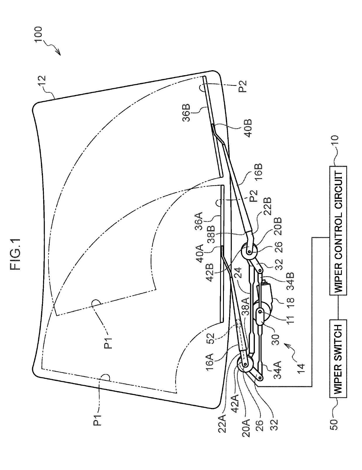
[0039]FIG. 1 is a schematic diagram illustrating configuration of a wiper device 100 according to an exemplary embodiment. The wiper device 100 is, for example, a device for wiping a windshield glass 12 provided to a vehicle such as a passenger car, using wiper blades 36A, 36B.

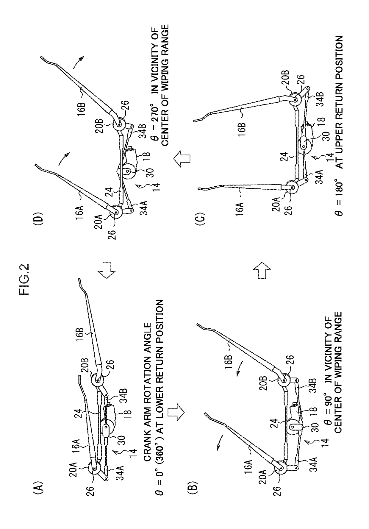
[0040]As illustrated in FIG. 1, the wiper device 100 includes a wiper motor 18, a link mechanism 14, and two wiper arms 16A, 16B. The wiper motor 18 drives rotation of a non-illustrated rotation shaft to drive rotation of an output shaft 11 through a speed reduction mechanism, configured by a non-illustrated worm gear and the like. The link mechanism 14 converts the rotational drive of the output shaft 11 into to-and-fro movement of two link rods 34A, 34B, described later. Base portions 42A, 42B of the wiper arms 16A, 16B are coupled to rotation shafts 26 that rotate in coordination with the to-and-fro movement of the link rods 34A, 34B. The wiper arms 16A, 16B are swung by rotation of the rotation shafts 26 s...


PUM


Abstract

A wiper device includes a wiper arm that includes a recess and that is swung due to rotation of a wiper motor, the wiper arm causes a wiper blade coupled to a leading end portion of the wiper arm to perform a wiping operation across a surface of a windshield glass, an acceleration sensor that is installed in the recess of the wiper arm, a drive circuit that generates a voltage to be applied to the wiper motor, and a control circuit that controls the drive circuit such that a voltage to reduce a change in acceleration of the wiper arm, detected by the acceleration sensor, is applied to the wiper motor.

Description

TECHNICAL FIELD[0001]The present disclosure relates to a wiper device.BACKGROUND ART[0002]In wiper devices in which a windshield glass is wiped by a wiper blade, the wiper blade sometimes vibrates with a shuddering motion during a wiping operation due to fluctuations in friction loading on the glass surface or fluctuations in the voltage from a battery configuring a power source. This vibration is referred to as “juddering”.[0003]Such juddering not only impairs wiping of the windshield glass surface, but is also a distraction to vehicle occupants, and so it is strongly preferable that this phenomenon does not occur in wiper devices. In the past, in order to suppress or eliminate juddering, additional components have been provided as countermeasures, repeated adjustments have been made to equipment through trial and error, and the voltage applied to a wiper motor has been raised to increase the wiping speed.[0004]However, with such trial and error it takes time and effort to produce ...

Claims


Application Information

Patent Timeline
Patent Type & Authority Applications(United States)
IPC IPC(8): B60S1/08B60S1/34
CPCB60S1/0822B60S1/28B60S1/0807B60S1/3425B60S1/08B60S1/0859B60S1/245B60S1/3429
Inventor IWASAKI, YUUTAHAIJIMA, TAKUJIOGASAWARA, HIROYATOMIDA, MITSUYOSHIHAYAKAWA, NATSUTO
Owner DENSO CORP
Why Eureka
Try Eureka